110
c Platemaking/Master Feed and Ejection Section
chap.3
(2)
Removal of End Mark Sensor PCB Unit
1. Open the scanner, and take out the master roll.
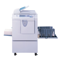
2. Open the master cover.
3. Remove the 2 screws, and remove the cover.
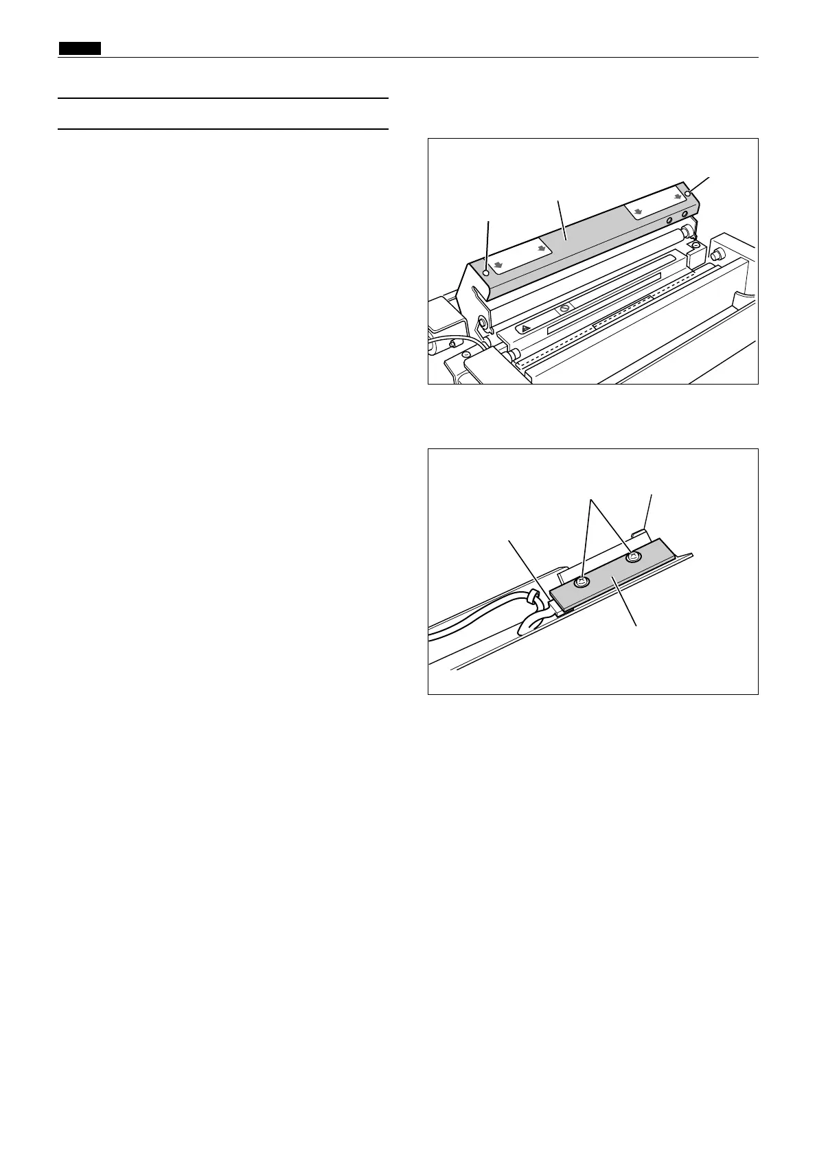
4. Remove the 2 screws.
5. Disconnect the connector indicated, and the end
mark sensor PCB unit.
 Loading...