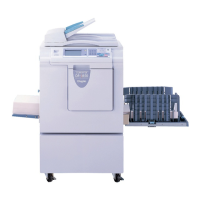
Attach the rear cover rib to the frame
and then fix the rear cover with the
screws.
IMPORTANT :
Reinstallation
100
z Exterior
chap.3
(4) Removal of Rear Cover
1. Remove the 4 screws indicated, then remove the
rear cover.
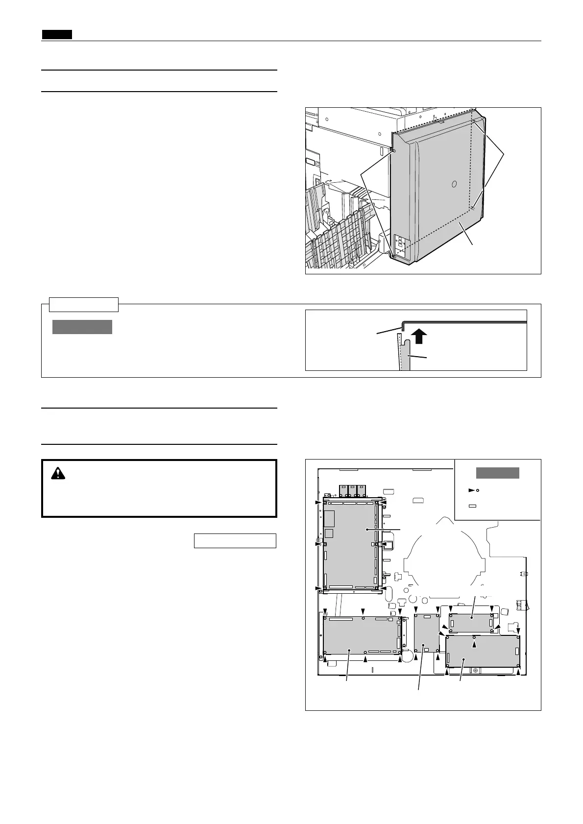
(5)
Removal of Main PCB Unit ,Drive PCB Unit ,
Relay PCB unit and Switching power supply 24V/5V
1.
Remove the front cover.
\See page 98
WARNING
¡Always remove the power cord plug from
the outlet before replacing a PCB Unit.
R8S03008
R8S03007
Screws
Rear cover
Main PCB unit
Relay
PCB unit
Screws
R8S03004a
Switching power supply ( 24V )
Switching power supply ( 5V )
Drive PCB unit
: screw
: connector
Example
Frame
Rear cover rib
2. Remove the connectors of.
¡ Main PCB unit
:
14 connectors
¡ Drive PCB unit
:
7 connectors
¡ Relay PCB unit
:
5 connectors
¡
Switching power supply ( 24v ) : 3 connectors
¡
Switching power supply ( 5v ) : 2 connectors
3. Remove the mounting screws, and replace the
PCB units.
¡ Main PCB unit
:
6 screws
¡ Drive PCB unit
:
6 screws
¡ Relay PCB unit
:
4 screws
¡
Switching power supply ( 24v ) :
5 screws
¡
Switching power supply ( 5v ) :
4 screws
 Loading...