103
z Exterior
chap.3
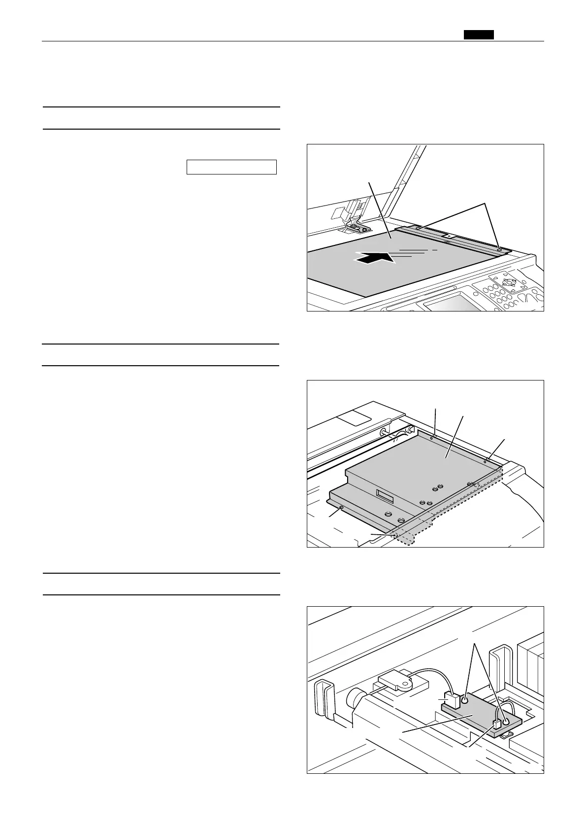
(2) Removal of Reading Cover
(3) Removal of Inverter PCB Unit
1. Perform steps 1 through 2 of procedure (2).
2. Disconnect the 2 connectors.
3. Remove the 2 spacers indicated, and remove the
inverter PCB unit.
1. Remove the glass.
2. Remove the 4 screws indicated, and remove the
reading cover.
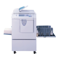
(1) Removal of Glass
1.
Remove the scanner side cover R.
2. Remove the 2 screws to take out the glass.
\See page 99
x Scanner Section
R8S03016
Screw
Reading cover
R8S03017
Spacers
Connector
Inverter PCB unit
Screw
Screw
Screw
Connector
R8S03015
Screws
Glass
 Loading...