182
zTroubleshooting Guide
chap.6
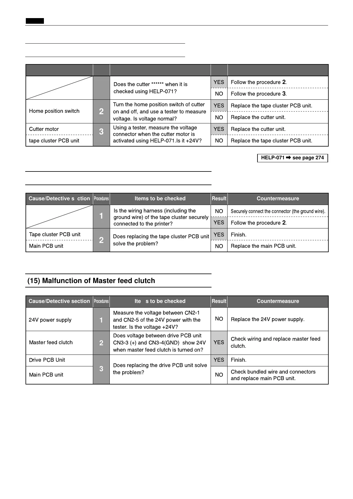
(13) "E020" is displayed
(14) "E021" is displayed
Cause/Detective section
Procedures
Result
CountermeasureItems to be checked
1
YES
Follow the procedure
3
.
Replace the cutter unit.
Home position switch
2
Turn the home position switch of cutter
on and off, and use a tester to measure
voltage. Is voltage normal?
YES Replace the tape cluster PCB unit.
Cutter motor
3
Using a tester, measure the voltage
connector when the cutter motor is
activated using HELP-071.Is it +24V?
YES Replace the cutter unit.
tape cluster PCB unit NO
NO
Does the cutter ****** when it is
checked using HELP-071?
Follow the procedure
2
.
Replace the tape cluster PCB unit.
NO
Cause/Detective section
Procedures
Result
CountermeasureItems to be checked
1
YES
Follow the procedure
2
.
Replace the main PCB unit.
Tape cluster PCB unit
Main PCB unit
2
Does replacing the tape cluster PCB unit
solve the problem?
YES Finish.
NO
Is the wiring harness (including the
ground wire) of the tape cluster securely
connected to the printer?
Securely connect the connector (the ground wire).
NO
HELP-071 \ see page 274
(15) Malfunction of Master feed clutch
Cause/Detective section
Procedures
Result
CountermeasureItems to be checked
24V power supply
1
Measure the voltage between CN2-1
and CN2-5 of the 24V power with the
tester. Is the voltage +24V?
NO
Replace the 24V power supply.
Master feed clutch
2
Does voltage between drive PCB unit
CN3-3 (+) and CN3-4(GND) show 24V
when master feed clutch is turned on?
YES
Check wiring and replace master feed
clutch.
Drive PCB Unit
3
Does replacing the drive PCB unit solve
the problem?
YES Finish.
Main PCB unit NO
Check bundled wire and connectors
and replace main PCB unit.