133
m Drum Section
chap.3
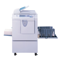
(9) Removal of Ink Detection PCB Unit
1. Remove the inner frame.
2. Pull out the connector.
3. Remove 2 screws to take out the ink detection
PCB Unit.
\See page 131
Confirm that the detection needle
is vertical with the PCB Unit and
does not contact anywhere, when
installing the Ink detection PCB
Unit.
IMPORTANT :
Reinstallation
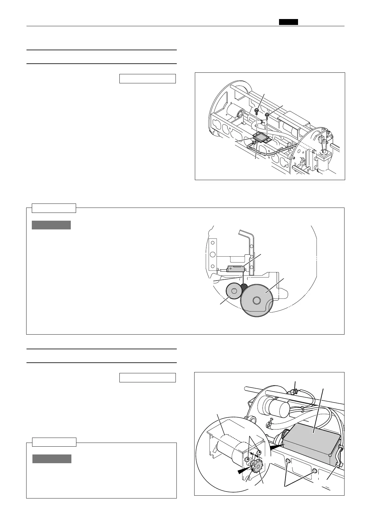
(10)
Removal of Ink Roller Up/Down Motor
1. Remove the inner frame.
2. Pull out the 2 connectors.
3. Remove 2 screws to take out the motor bracket.
4. Loosen the set screw to take out the gear.
5. Remove 3 screws to take out the ink roller
up/down motor.
\See page 131
Leave a space of 3 mm in the
section shown in the figure
when attaching the gear after
replacing the motor.
Reinstallation
IMPORTANT :
R8S03101
R8S03102
R8S03103
Motor bracket
Screw
Connector
Screw
Ink detection
PCB unit
Screws
Connector
Ink detection PCB unit
Ink roller
Squeegee roller
Detection
needle
Screws
Ink roller
up/down motor
Gear
Screw
Set screw
3mm
Connector
 Loading...