101
z Exterior
chap.3
R8S03011
Bracket
Connector
R8S03012
LCD panel
Screws
Screw
R8S03009
Control panel
Screw
R8S03010
Control panel
Connector
Panel board
Screw
Connector
Screws
Screw
Screw
Screw
Screw Screw
ScrewScrewScrew
Connector
Screws
Connector
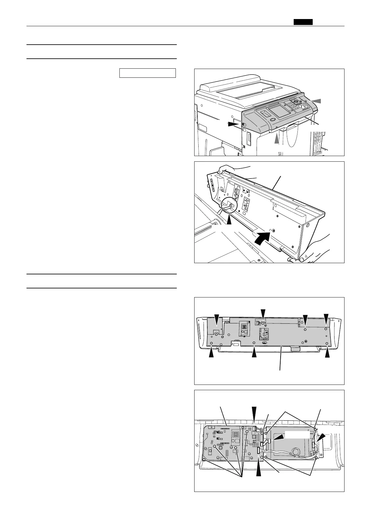
1. Remove the preciously mentioned 2 and 6.
2. Remove the 10 screws indicated, then remove
the bracket.
(7) Removal of Control Panel PCB
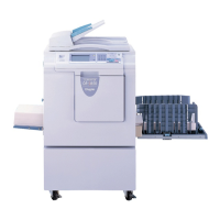
1. Remove the front cover.
\See page 98
(6) Removal of Control Panel
3. Remove the control panel by pulling up.
4. Remove the connector.
2. Remove the 3 screws.
3. Follow the instructions below to remove.
¡ Panel board
(3 connectors, 7 screws)
¡ LCD Panel
(3 connectors, 4 screws)
Screw
 Loading...