Working basis
22 Service Instructions 878-M PREMIUM - 03.0 - 10/2019
2. Turn the handwheel until the appropriate arresting groove (1) or (2) is
in front of the locking opening (4):
• Small arresting groove at handwheel position 0°
• Large arresting groove at handwheel position 200° – 205°
3. Insert the locking peg (3) with the appropriate end into arresting
groove (1) or (2).
Removing the lock
1. Pull the locking peg (3) out of arresting groove (1) or (2).
2. Insert the plug into the locking opening (4).
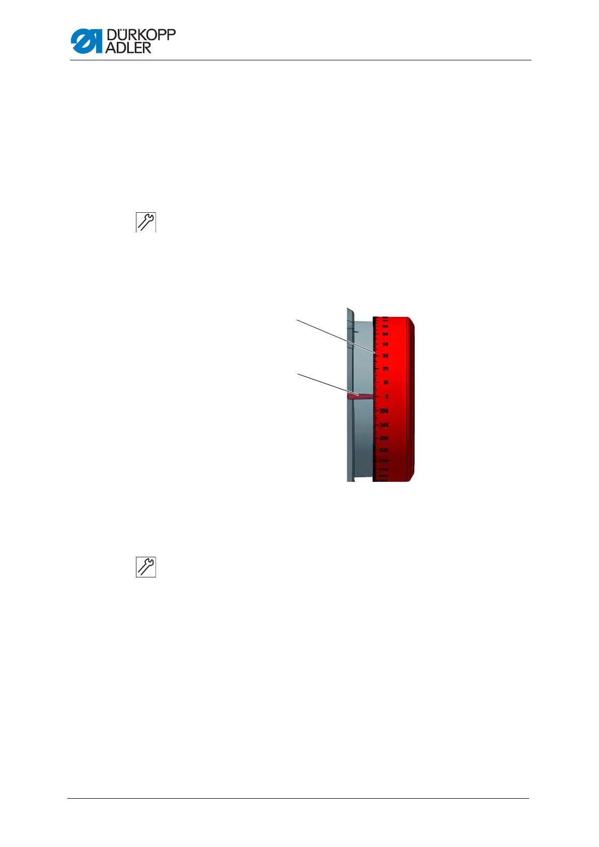
3.7 Setting the handwheel into position
Fig. 11: Setting the handwheel into position
For some settings, the graduated scale on the handwheel has to be
moved to a certain position.
1. Turn the handwheel until the specified number on the graduated scale
(1) is next to the marking point (2).
(1) - Graduated scale (2) - Marking point

 Loading...