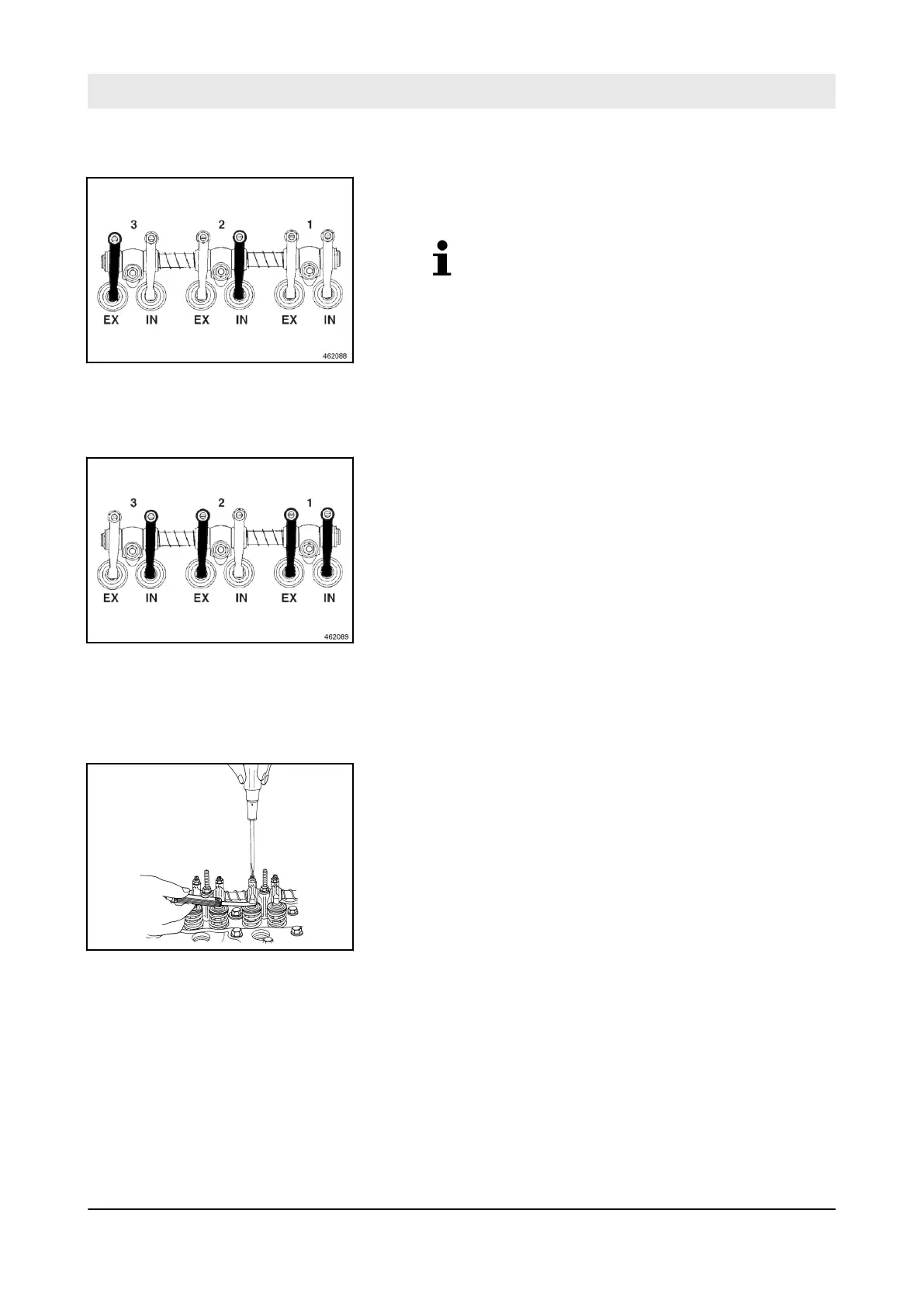
4. Turn the crankshaft using a V-belt until both valves on
cylinder 1 overlap.
Cylinder 1 is on the fan side.
5. Check the valve clearance on the valves marked black;
adjust if necessary.
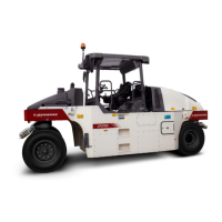
ð
The feeler gauge must fit through the gap with little resist-
ance.
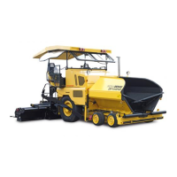
6. Turn the crankshaft one full turn (360 °) more using the V-
belt.
7. Check the valve clearance on the valves marked black using
a feeler gauge; adjust if necessary.
ð
The feeler gauge must fit through the gap with little resist-
ance.
8. Loosen the counter nut on the rocker arm.
9. Adjust the valve clearance using the adjustment screw.
10. Tighten the counter nut.
Checking the valve clearance
Fig. 163
IN Intake valve
EX Exhaust valve
Fig. 164
IN Intake valve
EX Exhaust valve
Adjusting the valve clearance
Fig. 165
Maintenance – Every 1000 operating hours
D.ONE
129