3.13. CPLD Architecture (For CPU Board)
3.13.1. Power Sequence
The most important function of the CPLD is to control the whole board power sequence based
on the power sequence requirement of Intel Broadwell-DE.
CPLD would base on the power good signals from the VRs on the board and then drives the
enable signals to enable the VRs.
The “PWROK” signals are used to indicate PCH and PCU of BDXDE that the related power are
ok.
3.13.2. Reset
There are three reset sources in the ES7654NT chassis: one is from BMC module as
“BMC_RST_BTN”, one is from MB as “MANU_RST”, the other one is from reset bottom on the
board.
When the three reset signals have been triggered, CPLD would announce the BDXDE CPU by
“PCH_SYSRESET_N” and let BDXDE PCU drive “PCH_PLTRST_N” to low to reset whole chassis.
Also, when the “BMC_PWR_BTN” is been driven from BMC or the the “SYS_PWRBTN_N” is
been driven by power button, the chassis would enter the sleep mode until the event has been
triggered again.
The “PCH_RSMRST_N” is used for power up sequence.
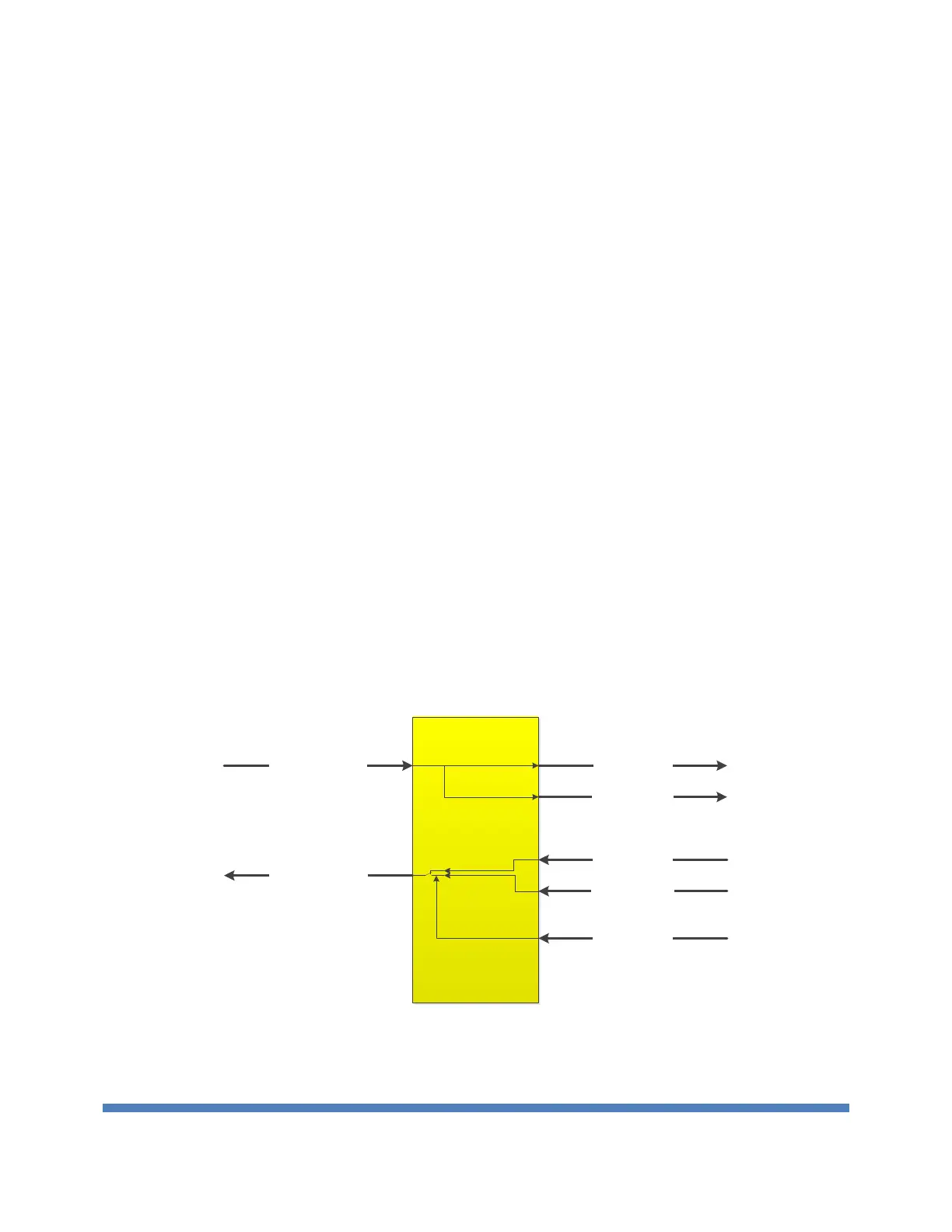
3.13.3. UART
The UART block is used to control the system UART message that would go to front panel
console port or connect to BMC.
When BMC_UART0_DIR_SEL is driven high, that allowed BMC to send UART message to CPU.
Figure 25 UART Overview
 Loading...