EDGECORE NETWORKS CORPORATION 2018
Selects the maximum operating rate of the PCI Express
interface:
2’b00: Interface can operate at PCI Express Gen1, Gen2, or
Gen3 speeds
2’b01: Interface can operate at PCI Express Gen1 speed
2’b10: Interface can operate at PCI Express Gen1, Gen2 speeds
(others): Reserved
Note: When the PCI Express interface is configured to support
Gen3 speeds, it is a requirement that the MHOST0_BOOT_DEV
strap signal is pulled high, the BOOT_DEV[2:0] signals are all
pulled low, and a QSPI flash memory is connected to the IP_QSPI
interface and contains the PCIe Gen3 microcode.
Selects the maximum link width of the PCI Express interface:
2’b00: Interface can operate at x1, x2, or x4 link widths
2’b01: Interface can operate at x1 link width only
2’b10: Interface can operate at x1 or x2 link widths
(others): Reserved
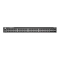
4.2. POR of MAC (BCM56873)
The detailed power-on reset (POR) flow is as follows:
1. The recommend power-up voltage sequence is from highest 3.3V to VDD1V0_ROV and 0.8V,
1.2V, 1.8V can ramp up until VDD1V0_ROV reaches 0.55V.
2. 3.3V : ramp up time min = 660us , max = 10ms.
3. VDD1V0_ROV : ramp up time min = 50us , max = 10ms.
4. 0.8V, 1.2V, 1.8V : ramp up time min = 100us , max = 10ms.
5. Minimum system reset de-asserted time is 80ms.
Figure 30 MAC Power-on Sequence
 Loading...