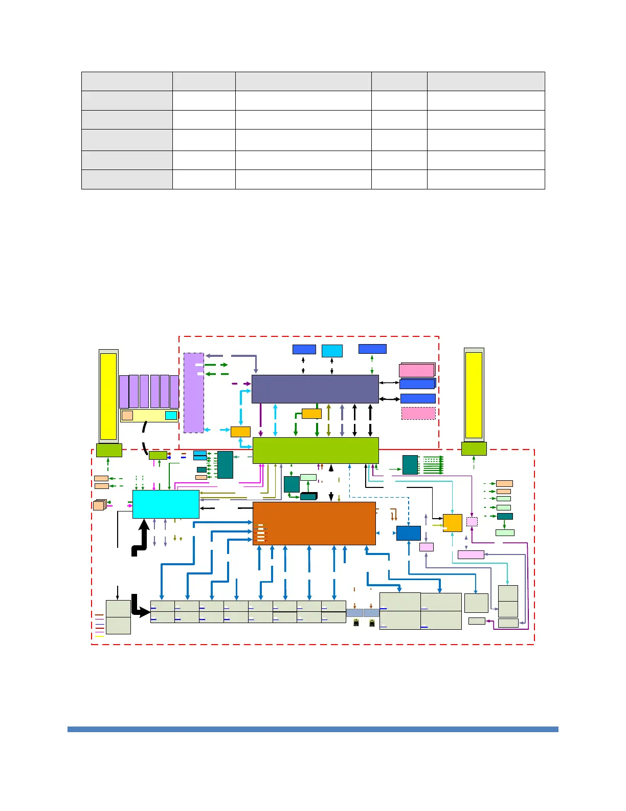
EasyManuals Logo

Edge-Core AS7326-56X Programming Guide

Edge-Core AS7326-56X
181 pages
To Next Page IconTo Next Page
To Previous Page IconTo Previous Page
Page #12 background imageLoading...
Page #12 background image
EDGECORE NETWORKS CORPORATION 2018
12
Component
Vendor
Quantity
Remark
Thermal Sensor
NS
3
USB HUB IC
SMSC
1
Power Monitor
Lattice
1
UART IC
TI
1
Transceiver
PSU (AC/DC)
3Y
2
650W AC
2.2. Block Diagram
The AS7326-56X provides 48 x 25G ports, 8 x 100G ports and 2 x 10G ports on the board
and can support 1 x 1G port for management and control. It is formed by BCM56873, a 20
Falconcore with max. 2T switch controllers. BCM56873 is connected to CPU module via PCIe
Gen2.0 x 4 bus. The host system includes two banks of 8GB DDR4 SO-DIMM, 16MB boot
Flash, Thermal detector, SYNC Ethernet and other glue logic. The Base unit uses 12VDC and
5VDC from the Hot swappable Power module. The on-board DC/DC is used to generate 3.3V/
1.8V/1.2V/i 1.2V/ 0.8V/0.8V(ROV) from 12VDC.
Figure 1 Switch board Block Diagram
Power
Module
BCM56873
156.25M_D
156.25M_D
156.25M_D
100M_D
50M_D
PCIe x
4
Power
Module
BCM54616
USB2.0
Mgmt
RJ45
SGMII
MDI
USB
Hub
USB
RS232
MDC/MDIO
UART
5V/0.2
12V/5A
CPLD X3
I2C_0
SYS_CPLD_INT_CPU
LED, MODSEL
,
MODPRSNT
, RESET
,INT
Switch board
PCB Brige
(12v, 3.3V, I2C, INT)
MANU_RST
MGMT_PHY_RST_N
MAC_RESET
_N
CPLD
Fan board
IP_LED_CLK[0:2]
0x60
0x62
0x64
0x66
System
LED
LOC
[B:G:R],DIAG
[B:G:R]
FAN
[B:G:R],PSU
1[B:G:R]
PSU
2[B:G:R]
LM75
X3
LM75
X3
LM75
X3
LM75BD_SCLK/SDA
INT_LM75 x3
P1014
0x25
FAN
_INT
_L
FAN
_SCL
_1
Connector
For Fan
12V/10A
3.3V/1A
0x54
MAC_RESET
_N
MGMT
_PHY_RST_N
PSU2
SMBUS:0x5B
EEPROM:0x53
PSU1
SMBUS:0x59
EEPROM:0x51
IR3595B
0x12
0x48~0x4A
PCA9548
CH0
CH1
CH2
CH3
CH4
CH5
CH6
CH7
CH0
RESET_SYS_CPLD
CPLD23_INT_CPU
0x71
Connector
For Power
Connector
For Power
CH4
SFP28*48
0x50
0x51
CH4
CH3
3.3V
1.8V
1.25V
1.0V
12V
5V
PCA9548
0x70
CH0
120 Pins BTB Connector
4056
FAN
4056
FAN
4056
FAN
4056
FAN
4056
FAN
4056
FAN
Fan1
Fan2 Fan3 Fan4 Fan5
Fan6
I2C_0
I2C_0_SCL_CPLD2
CH5
EEPROM
CPU module
2x1 10G
SFP+
LM75
0x4C
8V89307
SFP+ 0
CH5
DS100MB203
MUX
SFI x2
SFI
or
10G-KR x2
10G-KR x2
0x71~0x76
SERDES
SERDES
SERDES
1 x 2 25G
SFP28
3.3V
2 x 2 25G
SFP28
3.3V
1 x 2 25G
SFP28
3.3V
2 x 2 25G
SFP28
3.3V
1 x 2 25G
SFP28
3.3V
2 x 2 25G
SFP28
3.3V
1 x 2 25G
SFP28
3.3V
2 x 2 25G
SFP28
3.3V
1 x 2 25G
SFP28
3.3V
2 x 2 25G
SFP28
3.3V
1 x 2 25G
SFP28
3.3V
2 x 2 25G
SFP28
3.3V
1 x 2 25G
SFP28
3.3V
2 x 2 25G
SFP28
3.3V
1 x 2 25G
SFP28
3.3V
2 x 2 25G
SFP28
3.3V
1 x 2 100G
QSFP28
5W/port
3.3V
1 x 2 100G
QSFP28
5W/port
3.3V
1 x 2 100G
QSFP28
5W/port
3.3V
1 x 2 100G
QSFP28
5W/port
3.3V
SERDES
SERDES
SERDES
SERDES
SERDES
SERDES
SERDES
Reset
Bottom
Console
RJ45
SMB
10MHz OUT
SMB
1PPS OUT
IP_TS _GPIO1
IP_10MHZ_CL K
IP_10MHZ_CL K
IP_TS _GPIO1
PCA9548
CH7
QSFP28*8
0x50 0x51
0x72
USB
UART
RJ45
UART
RJ45
UART
XR21B1411ILTR
USB
UART
Consol
Micro USB
USB
CH1 CH2
8T49N240
0x7C
PCA9548
0x70
I2C_1
PCA9548
PCA9548
PCA9548
PCA9548
CH1
CH4
IR3595A
CH7
0x10
0x57
CH3
FAN_SCL_1/
SDA
CH3
CH2
CH6
LM75BD_S
CLK/SDA
CH6
0x50
0x51
SFP+ 0
CH6
0x50
0x51
Intel Boardwell-DE
Intel Xeon D-1518
SODIMM
Connector
DDR4
DDR4 RAM
8GB with ECC
10G-KR x 2
PCIe x 4
USB
UART
I2C
Reset GPIOs
TPM module
LPC
BCM5720
PCIe
BMC
module
RGMII
USB
UART
I2C
I2C
SATA
M.2
Connector
I2C
Slave
Master
M.2 SSD
32GB
SPI Flash
16MB
SPI
DDR4 RAM
8GB with ECC
SODIMM
Connector
MSata
Connector
SATA
I2C switch
Figure 2 CPU board Block Diagram

Table of Contents

Other manuals for Edge-Core AS7326-56X

Questions and Answers:

Question and Answer IconNeed help?

Do you have a question about the Edge-Core AS7326-56X and is the answer not in the manual?

Edge-Core AS7326-56X Specifications

General IconGeneral
BrandEdge-Core
ModelAS7326-56X
CategorySwitch
LanguageEnglish

Related product manuals