➢ IP_LED_clk/data1 provides port status for SFP+ ports 57-58.
Port status information includes link status, transmit and receive activity, and speed settings
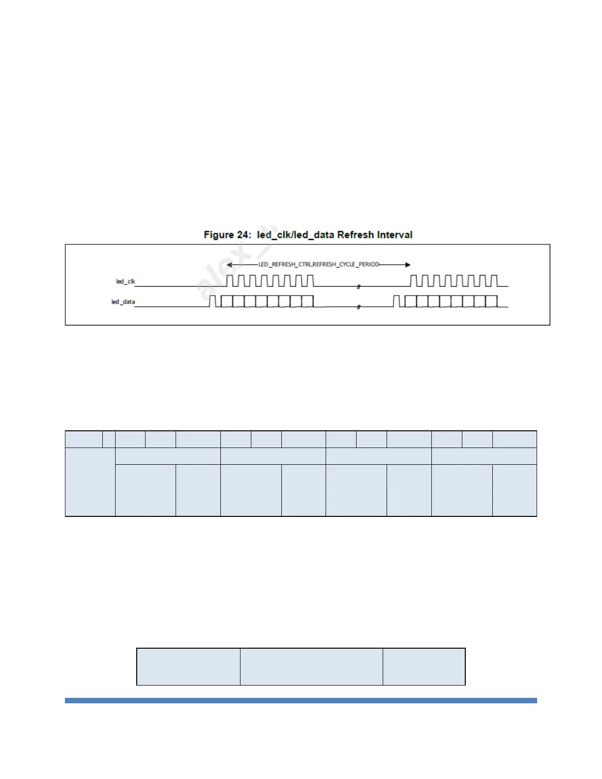
The interface to the LED status indicators is implemented through a serial protocol carried out on two
pins: LED_CLK and LED_DATA. If there are n LED status lights, it takes clock cycles to shift the data out
of the LED interface. The shifted-out LED data is out-of-phase with respect to the LED_CLK. After all n
bits have been shifted out, the LED_CLK and LED_DATA lines go idle until the next time the LED status
is refreshed. An external shift register is responsible for holding the state of the LED status between
scan (refresh) events.
Figure 33 LED bus
LED stream format:
There have four lanes per port. MAC will send lane[1:0] first, then send speed[1:0] and link-
up/activity information per lane. A port will have 14 bits information. A LED bus is for 16 ports, so
the total bits per led bus is 224 bits.
Table 18 LED stream format
Speed [1:0] shows the lane speed. Lane[1:0] shows the lane number for a port. So the lane[1:0]
and speed[1:0] shows the port configuration.
The bit of link-up/ Activity control the LED on/ off / toggle.
Table 19 LED Bit Description
 Loading...