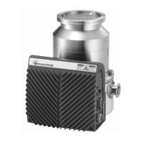
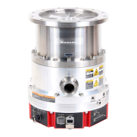
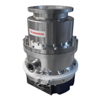
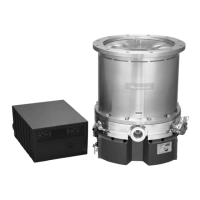
STP-iXA2205 Series Turbomolecular Pump
Nov. 10 ii Issue 1-h
PAGE
ii
CONTENTS (CONTINUED)
Section Title Page
3.8 Cable connection 50
3.8.1 DC cable 50
3.8.2 Power cable 51
3.8.3 How to connect the cables 53
3.9 Precautions of vacuum piping 55
3.9.1 Vacuum piping method 55
3.10 Connecting the purge port 56
3.11 Connecting the water cooling pipe 57
3.12 Attaching a baking heater 58
3.13 Installation of the TMS unit 59
3.13.1 Configuration of the STP pump with the TMS 59
3.13.2 TMS heater 61
3.13.3 TMS valve 61
3.13.4 Installation of the TMS unit 61
3.13.5 Connecting the TMS heater cable 61
3.13.6 Connecting the pump and TMS valve 62
3.13.7 TMS unit specification 62
3.14 Connecting to semiconductor equipment 63
3.14.1 Connecting to power 63
3.14.2 Emergency off circuit (EMO circuit) 63
4 OPERATION 65
4.1 Gas pumping, cooling and baking the STP pump 65
4.1.1 Gas pumping 65
4.1.2 How to introduce a purge gas 66
4.2 Cooling the STP pump 66
4.2.1 Water-cooling method 66
4.3 Baking the STP pump 67
4.4 Before starting the STP pump 68
4.4.1 Confirmation before starting 68
4.4.2 Confirmation of vacuum system 68
4.5 Powering ON 69
4.6 Pump operation 69
4.6.1 Input operation port setting 69
4.6.2 Starting/stopping the STP pump 70
4.7 How to start/stop the STP pump 72
4.7.1 Starting the STP pump after stopping 72
4.7.2 Starting the STP pump after a safety function operates 72
4.7.3 Powering OFF 72
4.8 LED 73
4.9 Parallel port input/output signal 74
4.9.1 Input signal pins 74
4.9.2 Input operation port setting 81
4.9.3 Rotation INHIBIT signal 82
4.9.4 OUTPUT SIGNAL PINS 83
4.10 Operating the TMS unit (for use with the TMS unit) 87
4.10.1 Before starting 87
4.10.2 Starting/Stopping 87
4.10.3 Setting the TMS unit function 87
 Loading...


