Troubleshooting
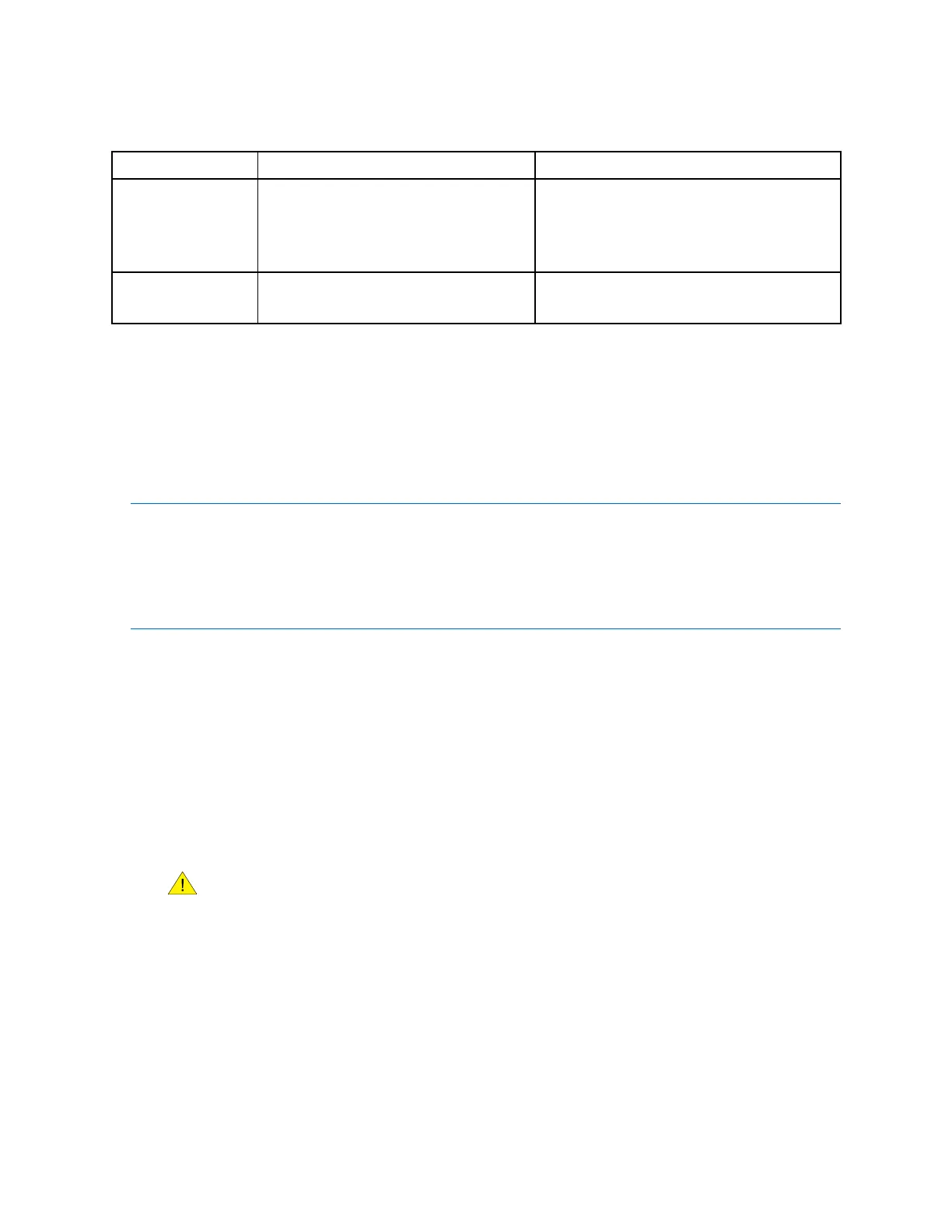
Table10-7Frequencyoutputproblemsandrecommendedactions
continued
ProblemPossiblecausesRecommendedactions
Consistently
incorrectfrequency
measurement
•Outputnotscaledcorrectly
•Incorrectowmeasurementunit
congured
•Checkthefrequencyoutputscaling.See
Section10.20.
•Verifythatthemeasurementunitsare
conguredcorrectlyforyourapplication.
Erraticfrequency
output
•RF(radiofrequency)interference
fromenvironment
•Checkforradiofrequencyinterference.
SeeSection10.12.
10.8Usesensorsimulationfortroubleshooting
Youcanusesensorsimulationtohelpdistinguishbetweenlegitimateprocessnoiseandexternally
causedvariation.Forexample,considerareceivingdevicethatreportsanunexpectedlyerraticow
value.Ifsensorsimulationisenabledandtheobservedowratedoesnotmatchthesimulatedvalue,
thesourceoftheproblemislikelytobesomewherebetweenthetransmitterandthereceivingdevice.
Important
Whensensorsimulationisactive,thesimulatedvalueisusedinalltransmitteroutputsandcalculations,
includingtotalsandinventories,volumeowcalculations,andconcentrationcalculations.Donotenable
simulationmodeunlessyourapplicationcantoleratetheseeffects,andbesuretodisablesimulation
modewhenyouhavenishedtesting.
10.9Checkpowersupplywiring
Prerequisites
Toverifywiring,youwillneedacopyoftheinstallationmanualforyourtransmitter.Tocheckpower
supplywiringforthe
9739MVDtransmitter,youmustremovetheelectronicsmodulefromthe
transmitterhousingbase.
Procedure
1.Beforeinspectingthepowersupplywiring,disconnectthepowersource.
Ifthetransmitterisinahazardousarea,waitveminutesafterdisconnectingthe
power.
2.Verifythatthecorrectexternalfuseisused.Anincorrectfusecanlimitcurrenttothetransmitter
andkeepitfrominitializing.
3.Ensurethatthepowersupplywiresareconnectedtothecorrectterminals.
4.Verifythatthepowersupplywiresaremakinggoodcontact,andarenotclampedtothewire
insulation.
5.Inspectthevoltagelabelontheinsideoftheeld-wiringcompartment.
Thevoltagesuppliedtothetransmittershouldmatchthevoltagespeciedonthelabel.
6.Reapplypowertothetransmitter.
190MicroMotion9739MVDTransmitters

 Loading...


