Setup & Operation 12. Option Units
RC180 Rev.17 91
Board Configuration (CC-Link)
Configuration of the device station is available with the station configure switch on the
CC-Link board.
Baud rate configuration is available with baud rate configure switch on the CC-Link
board.
(1) Set the station of the CC-Link board with the station configuration switch.
Make sure that the station does not duplicate with the other devices inside the network
at configuration.
Switches on the ×10 side are for tens place address value configuration. Switches on
the ×1 side are for units digit address value configuration. Stations from 1 to 62 are
available. CC-Link board occupies three stations. Assign the configured stations
+3 stations to the next node.
(2) Set the CC-Link baud rate. Check the master configuration and set the same baud
rate. Refer to the following table for configuration.
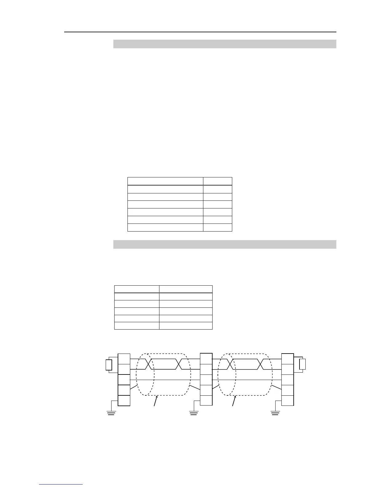
Wiring (CC-Link)
The CC-Link connector is a 5 pin open connector. Use the connector attached to the
board for wiring.
Terminal name for each pin