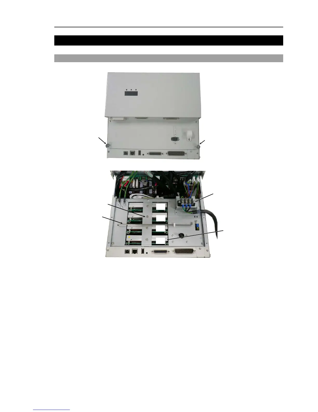
EasyManuals Logo

Epson RC180 User Manual

Epson RC180
264 pages
To Next Page IconTo Next Page
To Previous Page IconTo Previous Page
Page #131 background imageLoading...
Page #131 background image
Maintenance 3. Controller Structure
RC180 Rev.17 119
3. Controller Structure
3.1 Location of Parts
(1)
(1)
(2)
(3)
AC Terminal Block
This area contains high voltage.
Turn OFF and unplug the power
supply during the procedure.
[1]
[2]
[3]
[4]
Motor Driver
[1]Axis 1
[2]Axis 2
[3]Axis
3
[4]Axis
4
(1) Thumb Head screws
These are two of the four screws used to mount the front cover of the Controller.
These screws are also used to pull out the Motor Driver module and CPU board unit.
(2) Motor Driver Mounting Bracket
This is a bracket is used to secure the four motor drives. Make sure that each Motor
Driver is connected properly and then mount the bracket. Improper connection may
cause not only improper function of the robot system but also safety problems.
(3)
Front Side Supporting Bar
This supporting bar is used to hold the front cover open. Make sure that the
supporting bar is in the proper position.

Table of Contents

Other manuals for Epson RC180

Questions and Answers:

Question and Answer IconNeed help?

Do you have a question about the Epson RC180 and is the answer not in the manual?

Epson RC180 Specifications

General IconGeneral
BrandEpson
ModelRC180
CategoryController
LanguageEnglish

Related product manuals