Maintenance 6. Maintenance Parts Replacement Procedures
164 RC180 Rev.17
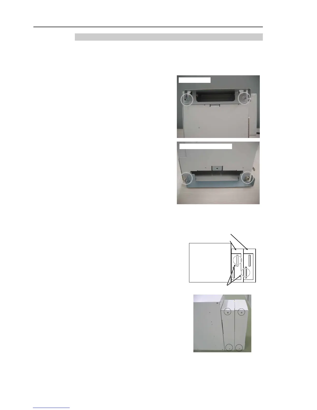
6.7.4 Mount Option Unit 2
When adding Option Unit 2
: Perform steps (1) to (8).
When replacing Option Unit 2: Perform steps (3) to (7).
Remove the fan filters (two places) of Option Unit 1 and mount Option Unit 2.
Maintenance 6.1.3 Cleaning and Replacing Fan Filter
Secure the Option Unit mounting
brackets to Option Unit 1 with four
screws.
The shape of the mounting bracket for
the top (DPB) and bottom (CPU board)
side are different. Be sure to mount
them
Secure Option Unit 2 with two screws each on front and backside.
two screws to remove the backside cover of the Option Unit 1.
Connect the flat cable connectors (two places)
to the backside of Option Units 1
Back of Controller
Main Part
Secure the covers to the backside of Option
Units 1 and 2 with two screws for each.
the cover so that there is no gap when
the power connector. Turn ON the Controller and make sure that the
Controller starts properly without any vibration or abnormal noise.