Setup & Operation 12. Option Units
RC180 Rev.17 73
12.2.3 Confirmation of Operation Using EPSON RC+ 5.0
When an expansion I/O board is mounted to the option unit, the Controller software
automatically identifies the expansion I/O board. Therefore, no software configuration is
needed.
Correct identification can be confirmed from EPSON RC+ 5.0.
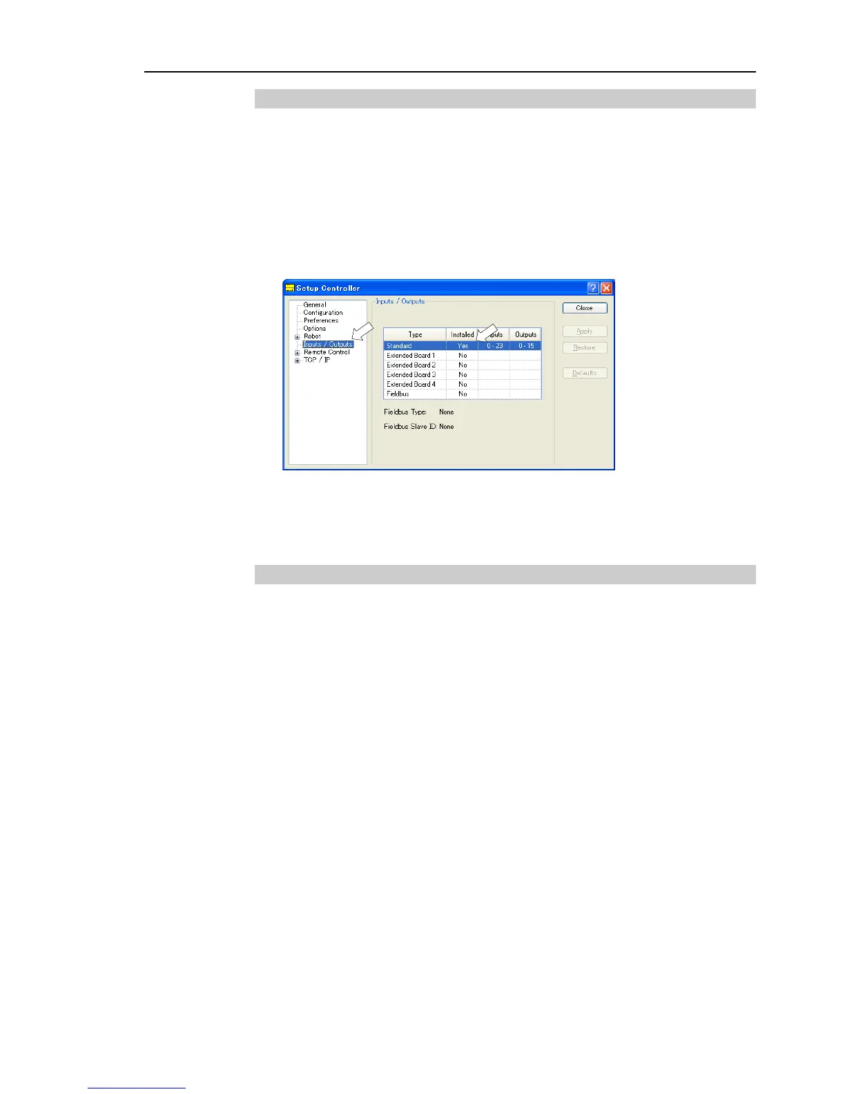
(1) Select the EPSON RC+ 5.0 menu-[Setup]-[Controller] to display the [Setup
Controller] dialog.
(2) Select the [Inputs / Outputs].
(3) Make sure that “Yes” is displayed in the Installed column.
The expansion I/O board is identified by the Controller software. Corresponding
Input and Output is available.
12.2.4 Input Circuit
Input Voltage Range : + 12 V to 24 V ±10%
ON Voltage : + 10.8 V (Min.)
OFF Voltage : + 5 V (Max.)
Input Current : 10 mA (TYP) at + 24 V input
Two types of wiring are available for use with the two-way photo coupler in the input
circuit.