Maintenance 6. Maintenance Parts Replacement Procedures
162 RC180 Rev.17
6.7.2 Mount Option Unit 1
Secure Option Unit 1 with two screws each on front side and backside.
Connect the flat cable connector to the backside of
Option Unit 1.
Back of Controller
Main Chassis
Secure the backside cover to Option Unit 1 with two screws.
the cover so that there is no gap when mounted.
the power connector. Turn ON the Controller and make sure that the
Controller starts properly without any vibration or abnormal noise.
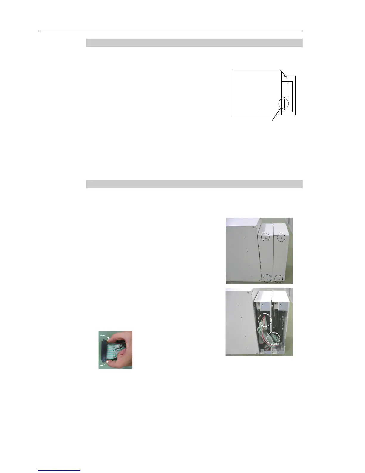
6.7.3 Remove Option Unit 2
Turn OFF the Controller and unplug the power connector.
Disconnect the cables connected to
Remove two screws on each unit from the
backside of Option Units 1 and 2 to remove the
covers.
Pull out the flat cable connector connected on
backside of Option Units 1 and 2.
the connector to pull out