**
Controller startup failure *1
**
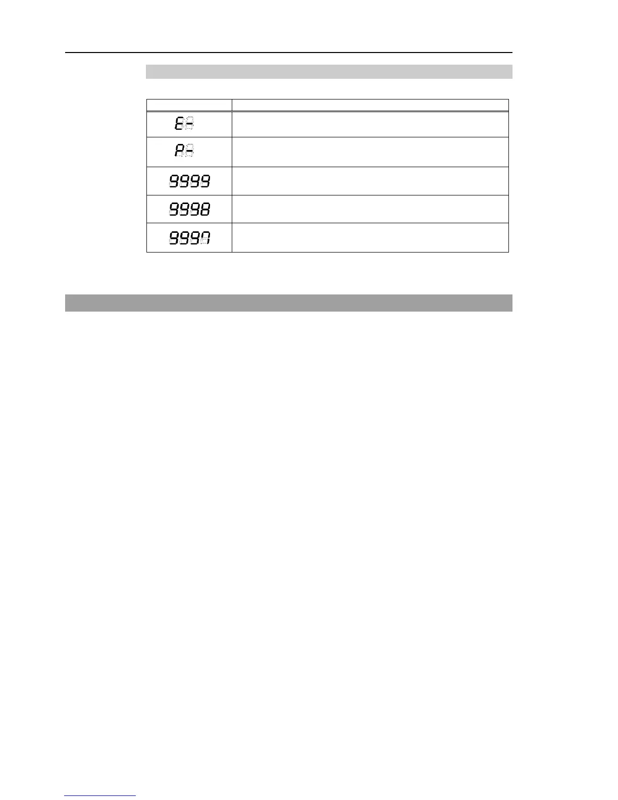
Controller startup failure
Controller in Recovery mode
Refer to Maintenance 4. Backup and Restore.
AC power supply drop is detected and software shut down.
(software) or the Teach Pendant (option).
*1 When the Initialize Error occurs, reboot the Controller. If the Initialize Error is displayed
again after the Controller is rebooted, please contact the supplier of your region.
2.4 Safety Features
The robot control system supports safety features described below. However, the user
is recommended to strictly follow the proper usage of the robot system by thoroughly
reading the attached manuals before using the system. Failure to read and understand
the proper usage of the safety functions is highly dangerous.
Among the following safety features, the Emergency Stop Switch and Safety Door Input
are particularly important. Make sure that these and other features function properly
before operating the robot system.
For details, refer to the Setup & Operation 9. EMERGENCY.
Emergency Stop Switch
The EMERGENCY connector on the Controller has expansion Emergency Stop input
terminals used for connecting the Emergency Stop switches.
Pressing any Emergency Stop switch can shut off the motor power immediately and the
robot system will enter the Emergency Stop condition.
Safety Door Input
In order to activate this feature, make sure that the Safety Door Input switch is connected
to the EMERGENCY connector at the Controller.
When the safety door is opened, normally the Manipulator immediately stops the current
operation, and the status of Manipulator power is operation-prohibited until the safety
door is closed and the latched condition is released. In order to execute the
Manipulator operation while the safety door is open, you must change the mode selector
key switch on the Teach Pendant to the “Teach” mode. Manipulator operation is
available only when the enable switch is on. In this case, the Manipulator is operated in
low power status.