Maintenance 6. Maintenance Parts Replacement Procedures
148 RC180 Rev.17
6.3 Motor Driver
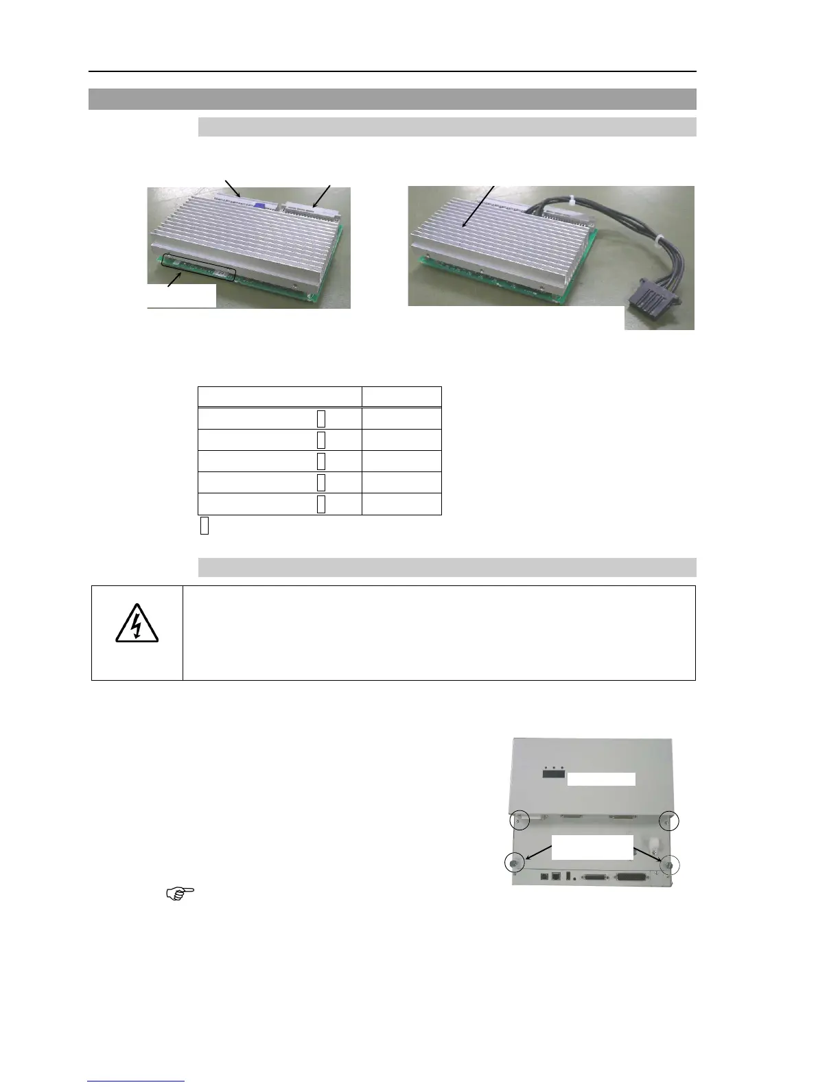
6.3.1 Part Names
Input/ Output Signal Connector
750W (With cable for dynamic brake resistor)
The wattage of the motor driver can be determined by the type code indicated on the
signature plate. The wattage of the installed motor driver corresponds with the wattage
of the driving motor.
JUSP-SU021A*
50 W
JUSP-SU028A*
100 W
JUSP-SU065A*
200 W
400 W
JUSP-SU169A*
750 W
* The asterisk indicates one alphanumeric character.
6.3.2 Replacing the Motor Driver (Axis 1 to 4)
WARNING
■
Be sure to record the type and the power rating (wattage) setting of the current
Motor Driver to set the correct power rating (wattage) when replacing the Motor
Driver.
Using a Motor Driver with improper power rating (wattage) in the Controller will
cause improper function of the robot system.
Turn OFF the Controller and unplug the power connector.
the following cables from the front
the Controller.
M/C Power Cable
M/C Signal Cable
EMERGENCY Cable
four screws shown in the photo.
thumb head screws are used to pull out the