Maintenance 6. Maintenance Parts Replacement Procedures
RC180 Rev.17 155
6.4 CPU Board Unit
The controller differs by the using manipulator. D
procedures are instructed for
each controller as follows. Follow the corresponding procedure.
Connected to the C3 or S5 series manipulator
Connected to the G or RS series manipulator
the Option Units if they are mounted.
Maintenance 6.7.1 Remove Option Unit 1
Maintenance 6.7.5 Remove Option Unit 1, 2
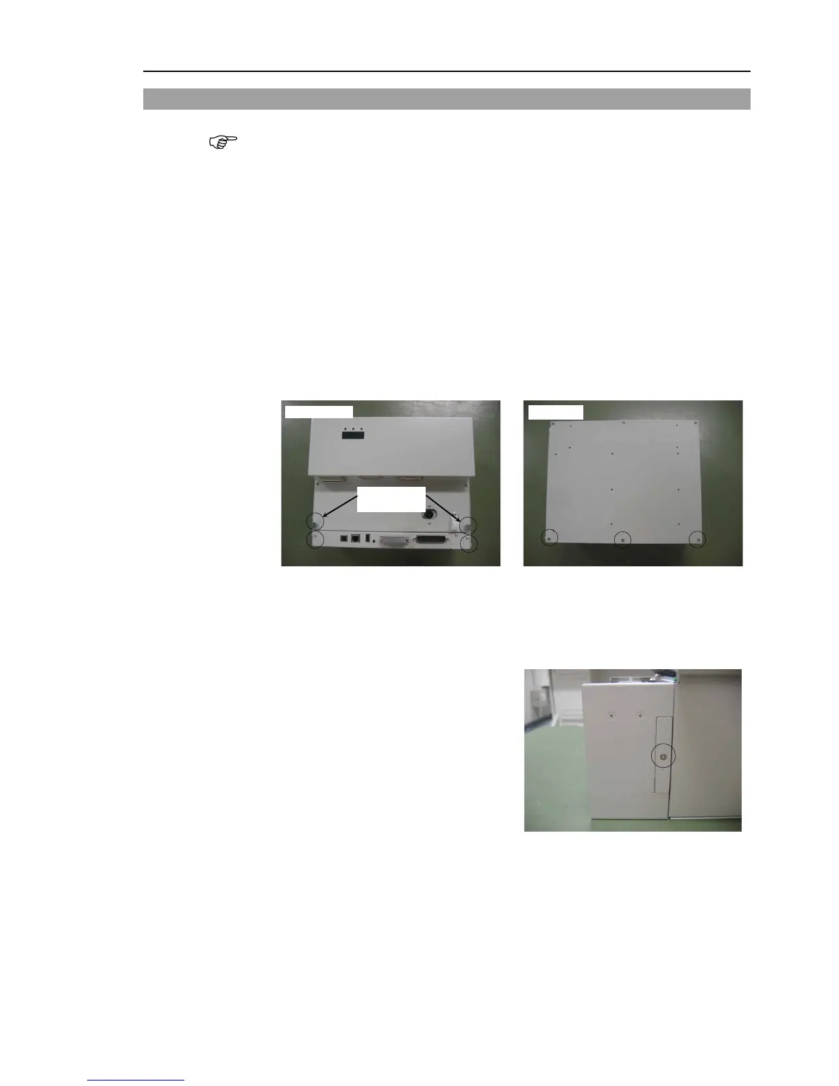
Turn OFF the Controller and unplug the power connector.
Disconnect the cables connected to the CPU board.
USB PC LAN USB memory TP/OP I/O
Remove four screws on the front cover and three screws on
the backside shown in the
Connected to the C3 or S5 series manipulator
Perform steps (4) to (6) to remove the ProSix Driver Unit.
G or RS series manipulator
Go on to step (7).
Remove the screw on the top and bottom
to remove the two covers.