Maintenance 6. Maintenance Parts Replacement Procedures
156 RC180 Rev.17
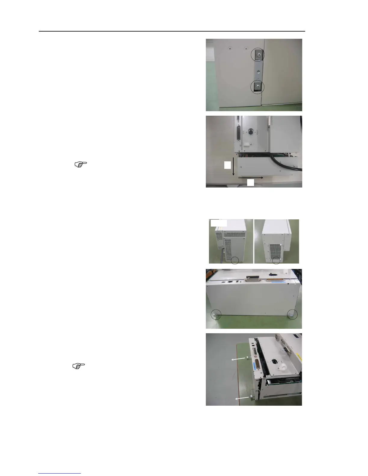
two screws on each cover.
Slide the ProSix Driver Unit
approximately 20 mm in direction (A)
and
then slowly slide it approximately 10
The ProSix Driver Unit cable is
connected to the main chassis. Be sure
to remove it slowly.
connected to the board connector.
Be sure to slide the ProSix Driver Unit
straight out in direction (A) as shown.
Remove the screws on both sides of the
CPU board unit.
two thumb head screws
removed in step (3) in the CPU board
unit.
Hold the thumb head screws and pull the
CPU board unit straight out.
The CPU board unit cable is connected to
the main
chassis. Be sure to remove
Disconnect the four connectors connected to the CPU board.
Maintenance 3.2 Diagram of Cable Connections
- Cable Layout Drawing