Maintenance 6. Maintenance Parts Replacement Procedures
RC180 Rev.17 157
four CPU board connectors.
Maintenance 3.2 Diagram of Cable Connections
- Cable Layout Drawing
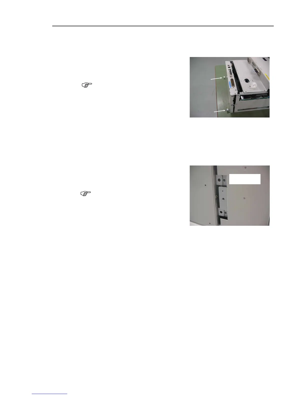
Carefully insert the CPU board unit by
pushing it
that connector CN2 of the
CPU Board and the DMB connector
(CPU IF) are connected
Be sure to keep the cable from being
trapped or damaged.
Mount the screw on each side of the CPU board.
Connected to the C3 or S5 series manipulator
Perform steps (4) to (6) to secure the ProSix Driver Unit.
Connected to the G or RS series manipulator
Move on to step (7).
Insert the ProSix Driver Unit into the
position.
Refer to the photo and be sure
position the mounting bracket properly
as shown.
Secure the ProSix Driver Unit with two screws on the top and bottom.
Secure the two covers with a screw of the top and bottom.
Secure each cover with the screws.
(Front cover : 4 screws, Backside : 3 screws)
Connect the following cables to the CPU
USB PC LAN USB memory TP/OP I/O
the power connector. Turn ON the Controller and make sure that the
Controller starts properly without any vibration or abnormal noise.