Setup & Operation 10. I/O Connector
RC180 Rev.17 61
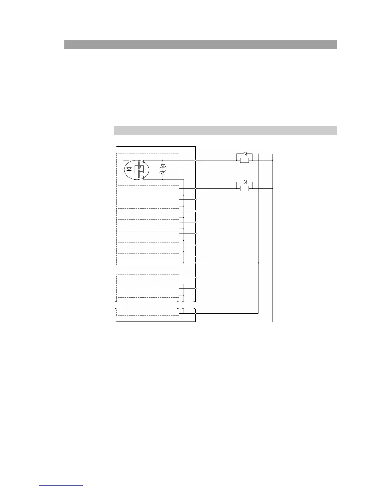
10.2 Output Circuit
Rated Output Voltage : +12 V to 24 V ±10%
Maximum Output Current : TYP 100 mA/1 output
Output Driver : PhotoMOS Relay
On-State Resistance (average) : 23.5 Ω or less
Two types of wiring are available for use with the nonpolar photoMOS relay in the output
circuit.
Typical Output Circuit Application 1