EasyManuals Logo

Epson RC180 User Manual

Epson RC180
264 pages
To Next Page IconTo Next Page
To Previous Page IconTo Previous Page
Page #122 background imageLoading...
Page #122 background image
Setup & Operation 12. Option Units
110 RC180 Rev.17
12.4.2 Board Setup (RS-232C)
Board Appearance
Switch and Jumper Configuration
CN1
CN2
CN3
CN4
JMP1
DSW2
DSW1
CN6
Set DSW1, DSW2 and JMP1.
CN6 is all open.
1
st
board
2
nd
board
SW4
SW3
SW2
SW1
DSW2
ON
1234
SW8
SW7
SW6
SW5
SW4
SW3
SW2
SW1
12345678
ON
DSW1
IRQ15
IRQ11
IRQ10
IRQ7
IRQ5
JMP1
JP5
JP4
JP3
JP2
JP1
1 2
CN6
1
2
9
10
SW4
SW3
SW2
SW1
DSW2
ON
1234
SW8
SW7
SW6
SW5
SW4
SW3
SW2
SW1
12345678
ON
DSW1
IRQ15
IRQ11
IRQ10
IRQ7
IRQ5
JMP1
JP5
JP4
JP3
JP2
JP1
1 2
CN6
1
2
9
10
12.4.3 Verify with EPSON RC+ 5.0 (RS-232C)
When an RS-232C board is mounted in as option unit, the Controller software
automatically identifies the RS-232C board. Therefore, no software configuration is
needed. Correct identification can be confirmed from EPSON RC+ 5.0.
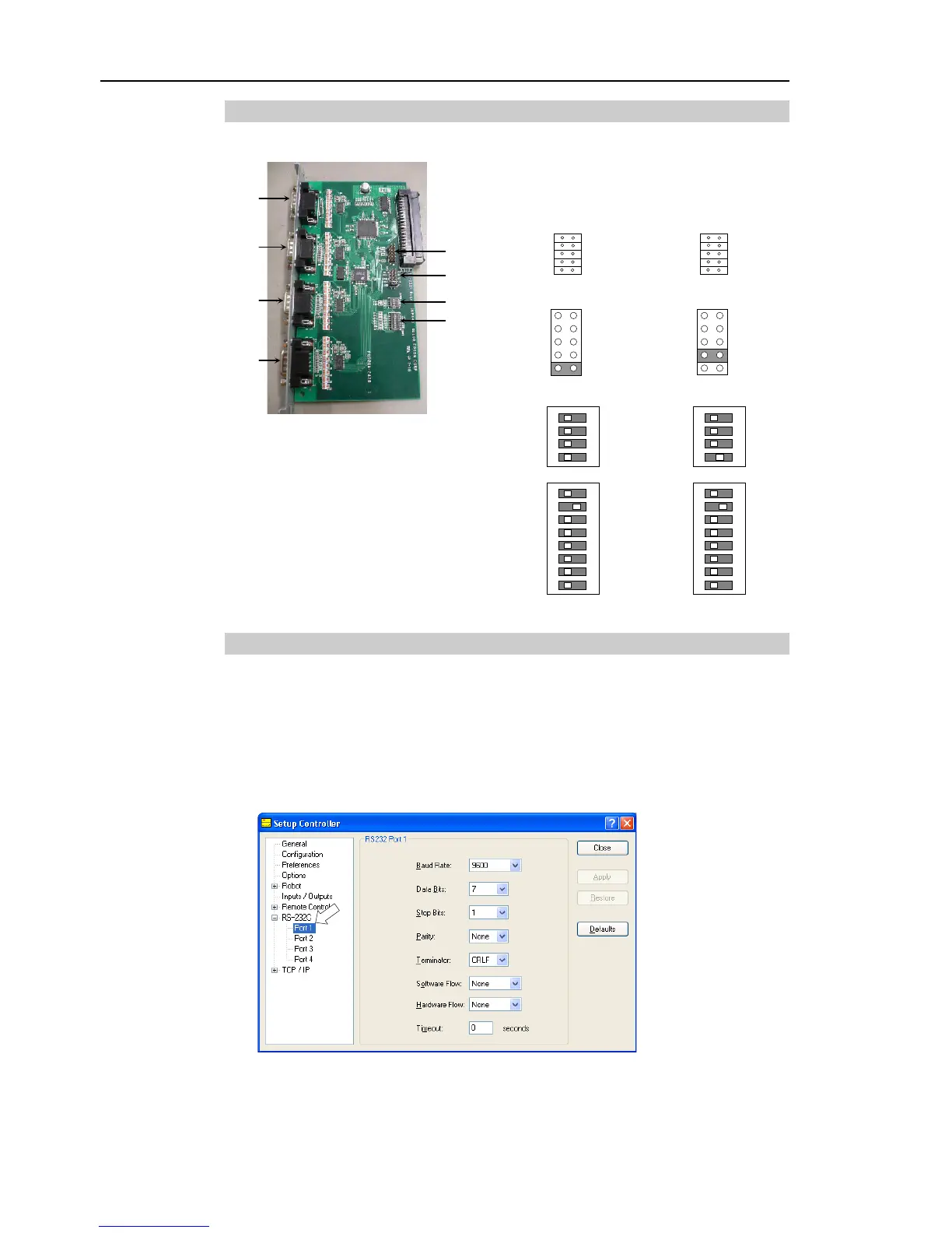
(1) Select the EPSON RC+ 5.0 menu-[Setup]-[Controller] to display the [Setup
Controller] dialog.
(2) Select the [RS-232C].
If no RS-232C board is identified, RS-232C will not be displayed.
If RS-232C is displayed, then the Controller software identified the RS-232C board.
Communication with external equipment is available.

Table of Contents

Other manuals for Epson RC180

Questions and Answers:

Question and Answer IconNeed help?

Do you have a question about the Epson RC180 and is the answer not in the manual?

Epson RC180 Specifications

General IconGeneral
BrandEpson
ModelRC180
CategoryController
LanguageEnglish

Related product manuals