Setup & Operation 3. Installation
RC180 Rev.17
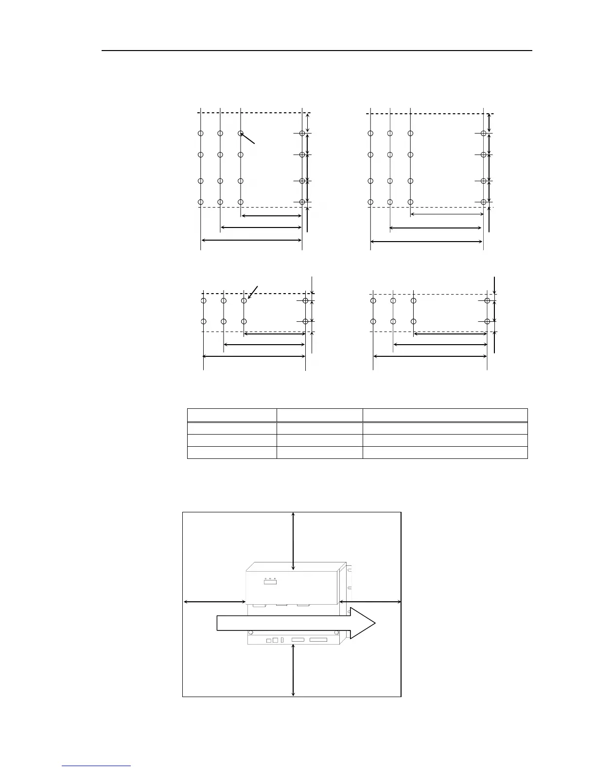
For Controller installation to the Controller box or the base table, process screw hole
drilling as follows.
When mounting direction is (A) or (B)
No screw hole processing is required for mounting direction (D).
Secure it to the rack with screws and nuts.
When mounting direction is (C) : Fixture S
Controller + ProSix Driver Unit
- Ensure the draft around the in/out and also install the Controller by keeping the distance
as follows to prevent the nose influence from other equipments such as large contactor
and relay.
Air flow of the Controller Fan
100 mm
Excluding the installation
side such as base table