SC-F2000 Revision C
ADJUSTMENT TF Adjustments 271
Confidential
[Blue]: Button or menu name on the program screen / [Black]: Button or menu name on the operation panel of the printer
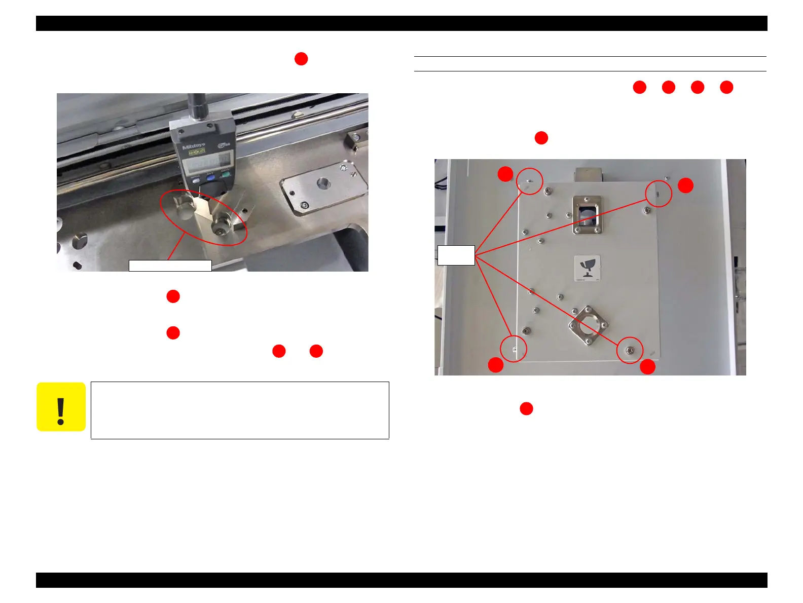
14. Set the gauge unit to the base at the measurement position with the concave
section on the gauge unit to the hole on the base.
Figure 4-83. Setting direction of the gauge
15. Measure the parallelism at and record the value.
16. Remove the gauge unit.
17. Measure the parallelism at and remove the gauge unit.
18. Move the TABLE ASSY and measure parallelism at and in the same
manner.
19. Calculate the difference between the maximum value and the minimum value
calculated in Step 15 to Step 18.
20. Evaluate the calculated difference for whether it is within the standard or not.
According to the judgment, follow the instruction in “Troubleshooting when color
unevenness and such occurs in the print area” (p.47). If the parallelism should be
adjusted, follow the procedure below.
PROCEDURE
Perform the adjustment one by one from the order of => => => . The
procedure is as follows.
1. Pull out the TABLE ASSY from the main body.
2. Loosen the fixing screw . (Do not loosen the other screws.)
Figure 4-84. Fixing screws
3. Set the gauge unit at to move parallel adjustment plate at measurement point.
4. Turn the adjustment screw (Figure 4-81) until the measurement value on the gauge
becomes approximately “0.00”.
When moving the TABLE ASSY, make sure to remove the gauge
unit from the base. Otherwise, the gauge unit may be damaged.
 Loading...


