Epson Stylus NX510/515/SX510W/515W/TX550W/NX415/SX410/415/TX410/419/NX215/SX210/215/TX210/213/219/ME OFFICE 510 Revision A
DISASSEMBLY/ASSEMBLY Differences in Disassembling/Reassembling SX210 series 154
Confidential
4.8 Differences in Disassembling/Reassembling
SX210 series
4.8.1 Main Board Unit (SX210 series)
Parts/Components need to be removed in advance
Document Cover/ASF Cover/Scanner Unit/Panel Unit/Upper Housing/Card Slot
Cover/Lower Housing
Removal procedure
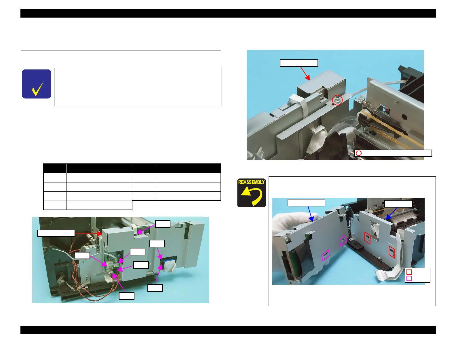
1. Disconnect the following connectors (x4) and FFCs (x3) from the Main
Board.
Figure 4-143. Removing the Main Board Unit (1)
2. Remove the screw (x1) that secures the Main Board Unit, and remove the
Main Board Unit.
Figure 4-144. Removing the Main Board Unit (2)
See the following because the disassembling/reassembling
procedures of the Main Board Unit for NX510/SX410 series differ
from those of SX210 series.
NX510 series: “ 4.4.1 Main Board Unit ” (p105)
SX410 series: “ 4.7.1 Main Board Unit (SX410 series) ” (p146)
CN No.
Cable
CN No.
Cable
CN1 Power Supply Unit cable CN9 PF Motor cable
CN5 Head FFC CN11 PF Encoder FFC
CN6 Head FFC CN24 PE Sensor cable
CN8 CR Motor cable
CN1
CN5
CN6
CN11
CN8
CN24
CN9
Main Board Unit
When installing the Main Board Unit, insert its hooks (x2)
into the cutouts (x2) of the Left Frame.
Figure 4-145. Installing the Main Board Unit
Tighten the screws in the order given in Figure 4-126.
C.B.S. 3x6, F/Zn-3C (4±0.5kgfcm)
Main Board Unit
Main Board Unit
Left Frame
Cutout
Hook
 Loading...