Epson Stylus NX510/515/SX510W/515W/TX550W/NX415/SX410/415/TX410/419/NX215/SX210/215/TX210/213/219/ME OFFICE 510 Revision A
DISASSEMBLY/ASSEMBLY Removing the Circuit Boards 111
Confidential
4.4.3 Power Supply Unit
Parts/Components need to be removed in advance
Document Cover/ASF Cover/Scanner Unit/Panel Unit/Upper Housing/Card Slot
Cover/Lower Housing
Removal procedure
1.
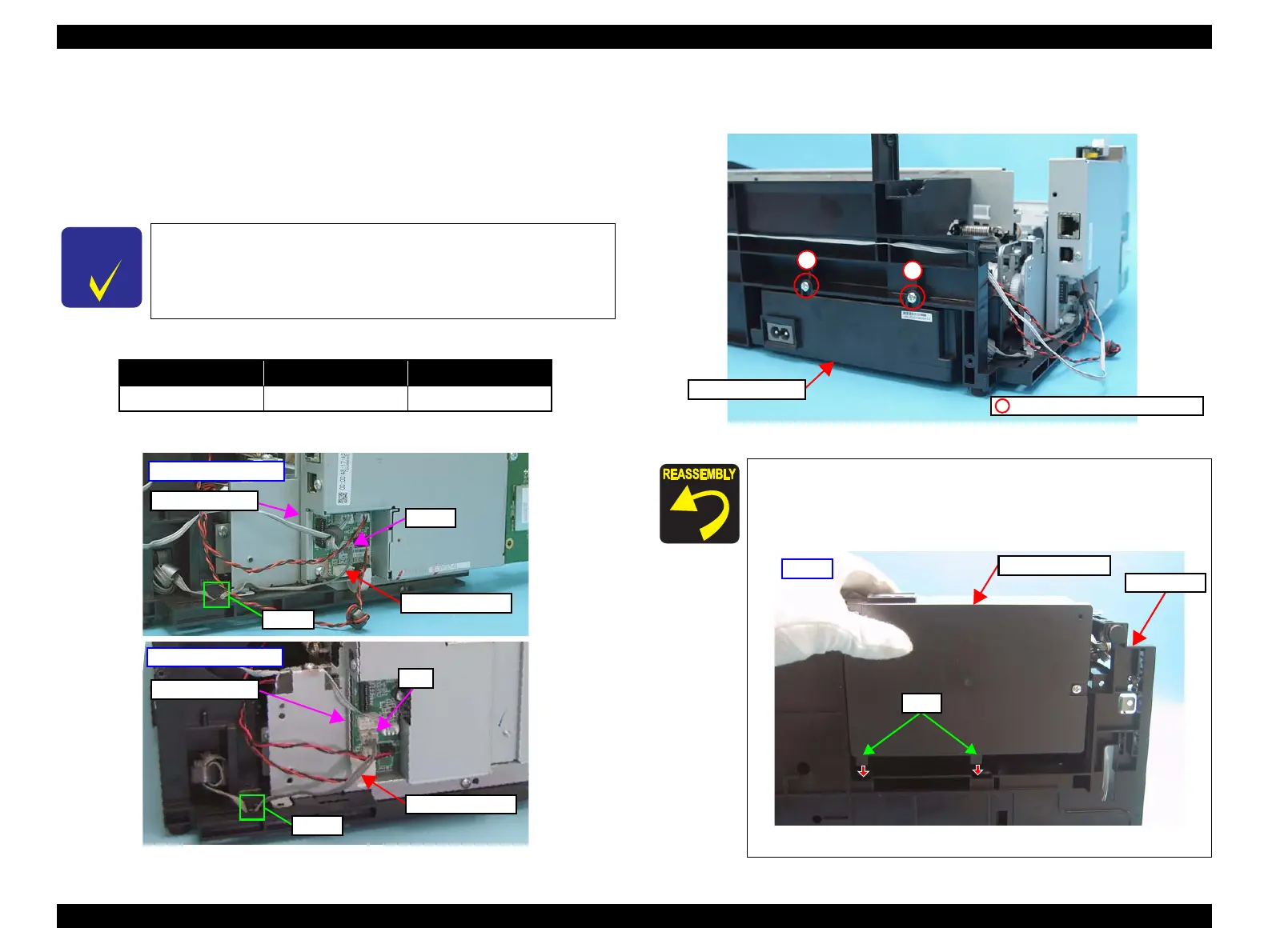
Disconnect the Power Unit Cable from the connector on the Main Board Unit below.
2. Release the Power Unit Cable from the hook of the Base Frame.
Figure 4-31. Removing the Power Supply Unit (1)
3. Remove the screws (x2) that secure the Power Supply Unit.
4. Lift the Base Frame a little, and remove the Power Supply Unit.
Figure 4-32. Removing the Power Supply Unit (2)
In this section, some disassembling procedures differ between
models. Skip the model-specified steps if not applied to your
model.
Item NX510 series SX410/SX210 series
Connector No. CN501 CN1
CN1
Main Board Unit
Hook
Power Unit Cable
SX410/SX210 series
CN501
Power Unit Cable
Hook
Main Board Unit
NX510 series
When installing the Power Supply Unit, make sure to check the
following point.
Insert the tabs (x2) of the Power Supply Unit into the holes on
the Base Frame.
Figure 4-33. Installing the Power Supply Unit
Power Supply Unit
C.B.P. 3x10, F/Zn-3C (6±1kgfcm)
1
2
Power Supply Unit
Tabs
Base Frame
Bottom
 Loading...