Epson Stylus NX510/515/SX510W/515W/TX550W/NX415/SX410/415/TX410/419/NX215/SX210/215/TX210/213/219/ME OFFICE 510 Revision A
DISASSEMBLY/ASSEMBLY Removing the Circuit Boards 105
Confidential
4.4 Removing the Circuit Boards
4.4.1 Main Board Unit
Parts/Components need to be removed in advance
Document Cover/ASF Cover/Scanner Unit/Panel Unit/Upper Housing/Card Slot
Cover/Lower Housing
Removal procedure
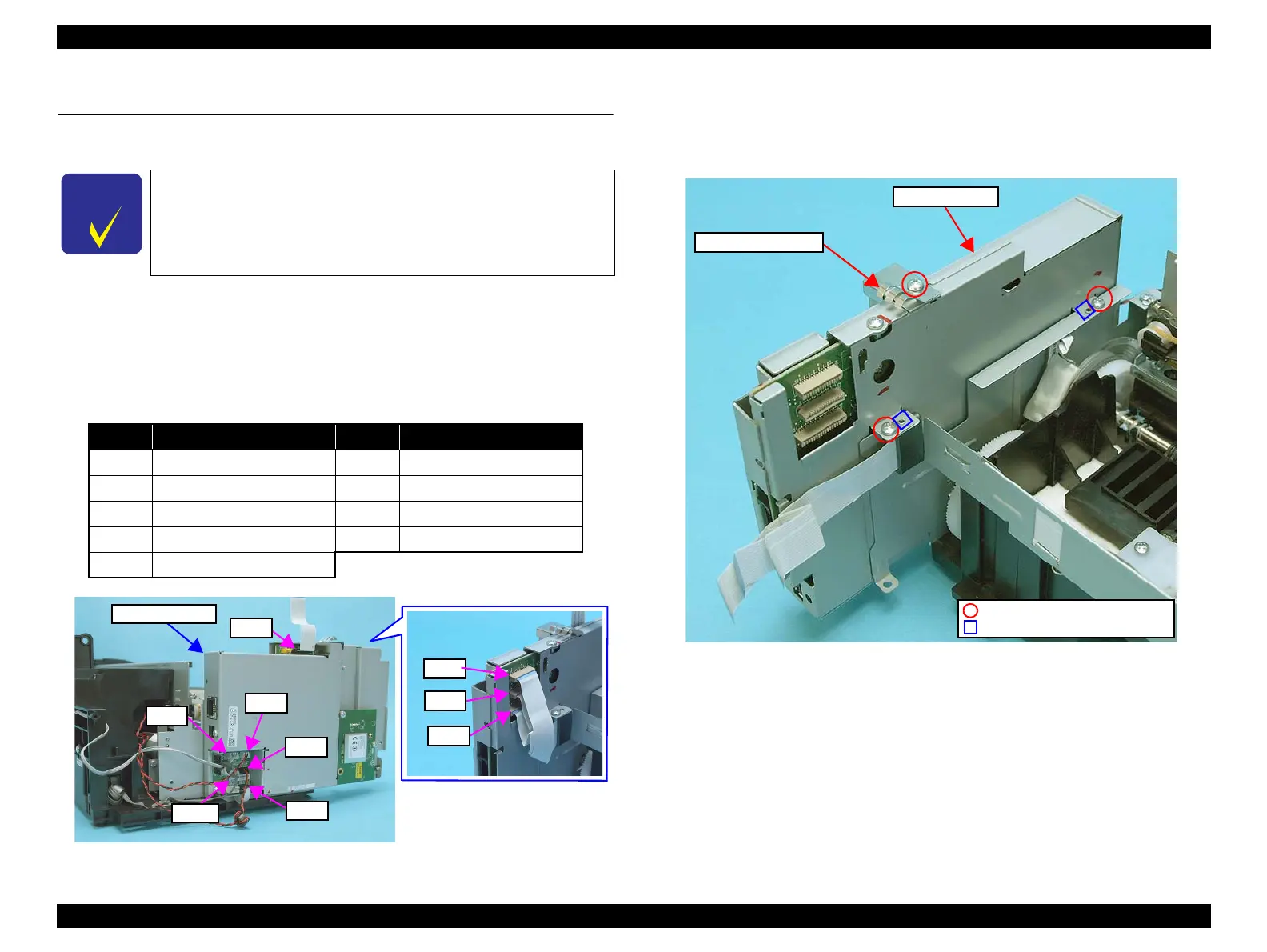
1. Disconnect the following cables (x4) and FFCs (x5) from the connectors on
the Main Board Unit.
Figure 4-18. Removing the Main Board Unit (1)
2. Remove the screw (x1) that secures the Panel Grounding Plate, and remove
the Panel Grounding Plate from the Main Board Unit.
3. Remove the screws (x2) that secure the Main Board Unit, and remove the
Main Board Unit.
Figure 4-19. Removing the Main Board Unit (2)
See the following because the disassembling/reassembling
procedures of the Main Board Unit for SX410/SX210 series differ
from those of NX510 series.
SX410 series: “ 4.7.1 Main Board Unit (SX410 series) ” (p146)
SX210 series: “ 4.8.1 Main Board Unit (SX210 series) ” (p154)
CN No.
Cable
CN No.
Cable
CN501 Power Supply Unit cable CN12 Head FFC
CN5 Panel FFC CN13 Head FFC
CN6 CR Motor cable CN14 PF Encoder FFC
CN7 PF Motor cable CN15 PE Sensor cable
CN11 Head FFC
C.B.S. 3x6, F/Zn-3C (4±0.5kgfcm)
Panel Grounding Plate
Main Board Unit
Positioning hole and dowel
 Loading...