Epson Stylus NX510/515/SX510W/515W/TX550W/NX415/SX410/415/TX410/419/NX215/SX210/215/TX210/213/219/ME OFFICE 510 Revision A
DISASSEMBLY/ASSEMBLY Differences in Disassembling/Reassembling SX210 series 158
Confidential
4.8.3 Printhead (SX210 series)
Parts/Components need to be removed in advance
Document Cover/ASF Cover/Scanner Unit/Panel Unit/Upper Housing
Removal procedure
1. Perform Step 1 to Step 8 of "4.5.1 Printhead (p113)".
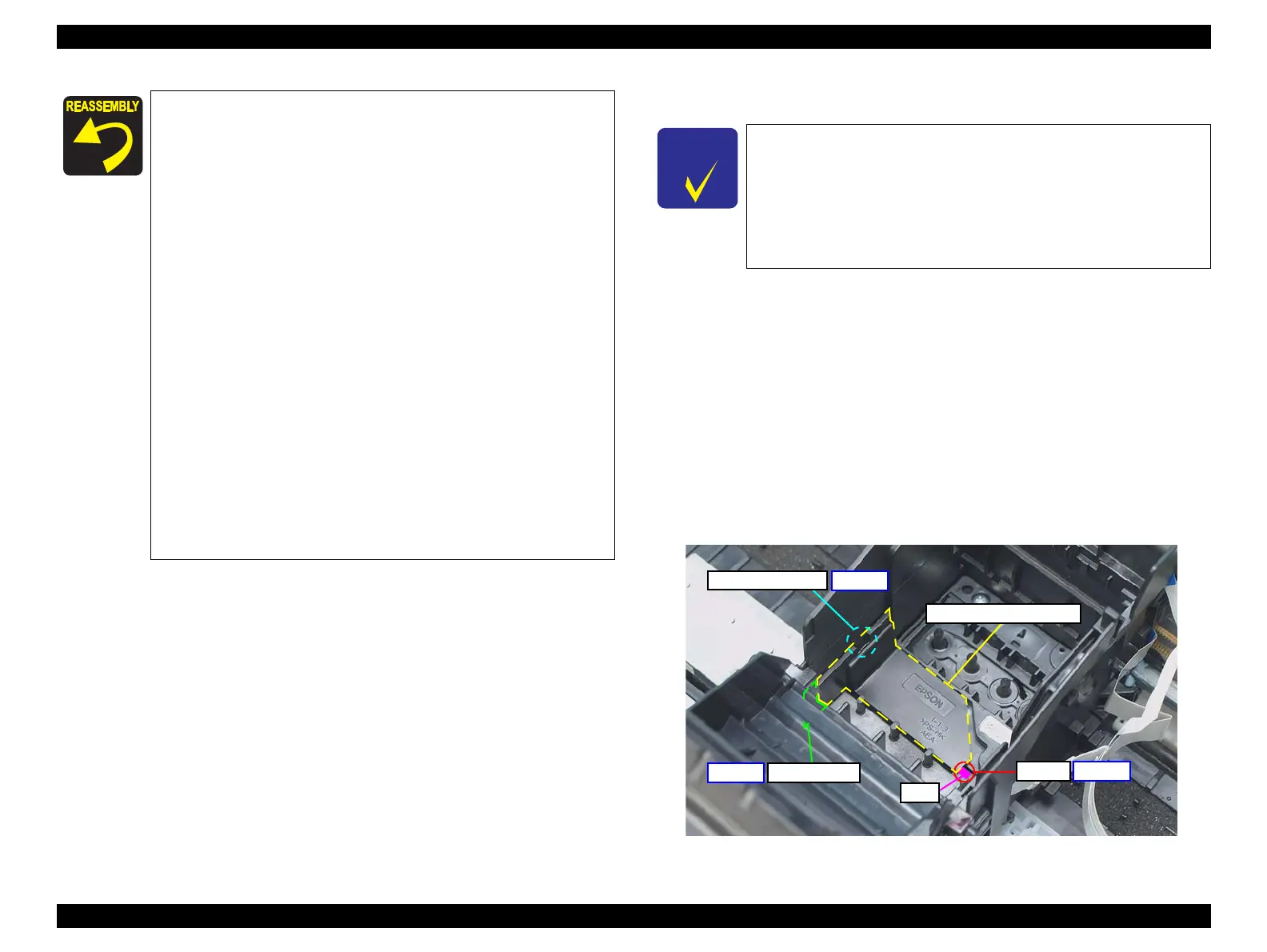
2. Remove the Head Cable Inner Cover according to the following procedure.
2-1. Release the cutout (x1) of the Head Cable Inner Cover from the hook
(x1) of the CR Unit.
2-2. Release the tab (x1) of the Head Cable Inner Cover from the groove
(x1) of the CR Unit.
2-3. Release the rib of the Head Cable Inner Cover from the cutout of the
CR Unit.
Figure 4-153. Removing the Sub FFC Guide
When installing each button, securely engage the hooks, or
align the dowels and the positioning holes correctly. After
assembling them, press all the buttons to confirm they sure
click. (See
Figure 4-152.)
When installing the LCD Unit, insert the ribs (x2) of LCD
Unit into the holes (x2) on the Panel Housing, and attach it
while aligning the positioning holes and pins. (See
Figure
4-151.)
When installing the Panel Board A/B, attach them while
aligning the positioning holes (x4) and the pins (x4). (See
Figure 4-150.)
When connecting the LCD FFC to the Panel Board B, lock
the connector (CN2) securely. (See
Figure 4-150.)
Tighten the screws in the order given in Figure 4-149. As for
the screw # 8, secure the grounding wire together.
When connecting the Panel FFCs (x2), align them with the
marking on Panel Board Frame, and secure them with
double-sided tape to the locations shown in
Figure 4-148
When attaching the grounding wire, make sure to put the
soldered section to the front of the printer, and secure it with
the screw. (See
Figure 4-147.)
When installing the Panel Unit, attach it without any gap with
the Upper Housing. (See
Figure 4-30.)
See the following because the disassembling/reassembling
procedures of the Printhead for NX510/SX410 series differ from
those of SX210 series.
NX510 series:
“ 4.5.1 Printhead ” (p113)
SX410 series:
“ 4.7.3 Printhead (SX410 series) ” (p150)
Head Cable Inner Cover
Cutout
Rib
Cutout and Hook
Step 2-1
Step 2-2
Step 2-3
Tab and groove
 Loading...