Epson Stylus NX510/515/SX510W/515W/TX550W/NX415/SX410/415/TX410/419/NX215/SX210/215/TX210/213/219/ME OFFICE 510 Revision A
DISASSEMBLY/ASSEMBLY Disassembling the Printer Mechanism 119
Confidential
4.5.5 Left Frame
Parts/Components need to be removed in advance
Document Cover/ASF Cover/Scanner Unit/Panel Unit/Upper Housing/Card Slot
Cover/Lower Housing/Main Board Unit
Removal procedure
1. For NX510 series: Peel off the double-sided tape that secures the ferrite core,
and remove the ferrite core from the Left Frame.
2. Remove the screws (x2), and remove the grounding plate.
3. Remove the screws (x3) that secure the Left Frame, and remove the Left
Frame.
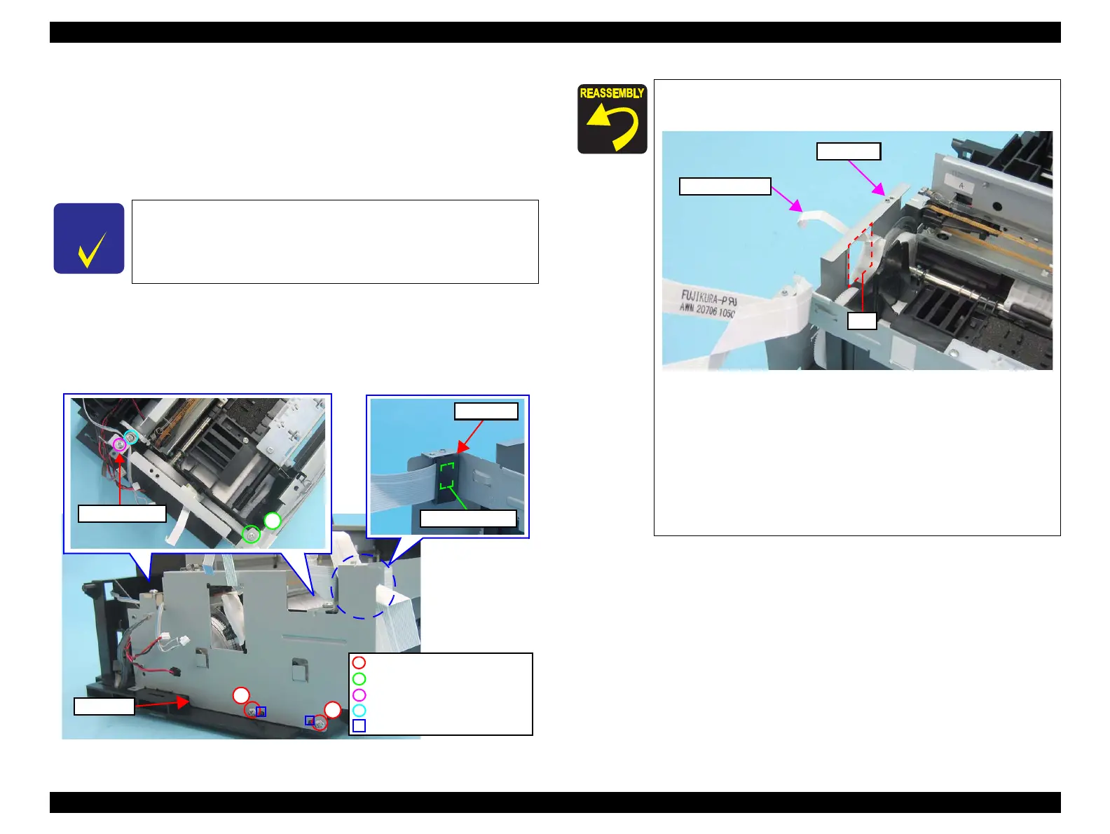
Figure 4-51. Removing the Left Frame
In this section, some disassembling procedures differ between
models. Skip the model-specified steps if not applied to your
model.
1
2
Left Frame
C.B.P. 3x8, F/Zn-3C (6±1kgfcm)
C.B.P. 3x6, F/Zn-3C (4±0.5kgfcm)
C.B.P. 3x10, F/Zn-3C (6±1kgfcm)
Positioning Hole and Guide Pin
Double-sided Tape
Ferrite Core
C.B.P. 3x6, F/Zn-3C (6±1kgfcm)
When installing the Left Frame, lead the PF Encoder FFC
through the hole of the Left Frame.
Figure 4-52. Routing the PF Encoder FFC
When installing the Left Frame, align the guide pins (x2) of
the Base Frame with their positioning holes (x2) of the Left
Frame as shown in
Figure 4-51.
NX510 series only:
When installing the Left Frame, attach the ferrite core to the
location shown in
Figure 4-51.
Tighten the screws in the order given in Figure 4-51.
Left Frame
PF Encoder FFC
Hole
 Loading...