Epson Stylus NX510/515/SX510W/515W/TX550W/NX415/SX410/415/TX410/419/NX215/SX210/215/TX210/213/219/ME OFFICE 510 Revision A
DISASSEMBLY/ASSEMBLY Differences in Disassembling/Reassembling SX410 series 148
Confidential
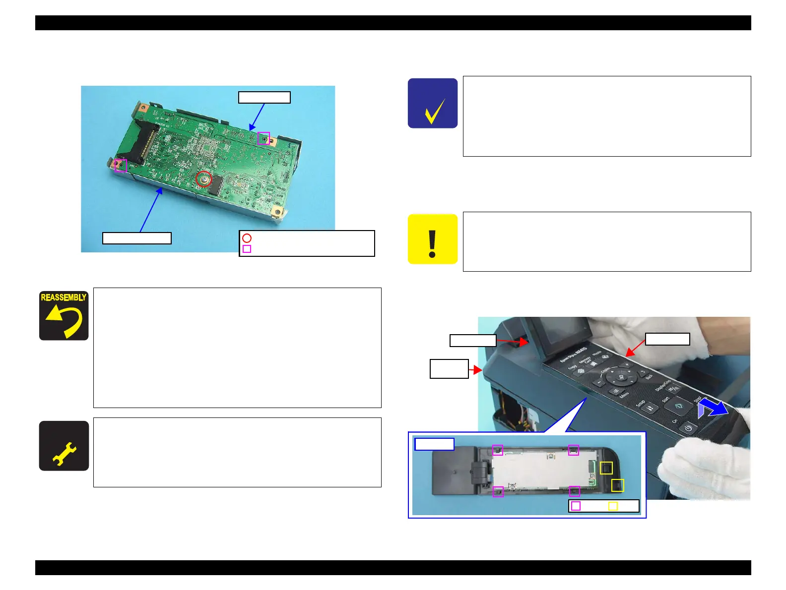
4. Remove the screw (x1) that secures the Main Board, and remove the Main
Board.
Figure 4-131. Removing the Main Board (2)
4.7.2 Panel Unit/LCD Unit (SX410 series)
Parts/Components need to be removed in advance: None
Removal procedure
1. Open the Scanner Unit
2. Raise the LCD Unit.
3. Lifting the front of the Panel Unit, and release the tabs of it.
4. Slide the Panel Unit in the direction of the arrow, and release the hooks of it
from the Upper Housing.
Figure 4-132. Removing the Panel Unit and LCD Unit (1)
When installing the Main Board,
pay attention to the following
instructions.
Align the positioning holes of the Upper Shield Plate with the
guide pins of the Main Board as shown in
Figure 4-131.
Align the positioning hole of the Main Board with the guide
pin of the MB Lower Shield Plate as shown in
Figure 4-130.
When installing the MB Lower Shield Plate, make sure that
the Upper Shield Plate is set over the MB Lower Shield Plate
as shown in
Figure 4-130.
A D J U S T M E N T
R E Q U I R E D
Whenever the Main Board is removed/replaced, the required
adjustments must be carried out.
• Chapter 5 “ ADJUSTMENT” (p.161)
C.B.S. 3x10, F/Zn-3C (4±0.5kgfcm)
Positioning Hole and Guide Pin
Upper Shield Plate
Main Board
See the following because the disassembling/reassembling
procedures of the Panel Unit/LCD Unit for NX510/SX210 series
differ from those of
SX410 series.
NX510 series:
“ 4.4.2 Panel Unit/LCD Unit ” (p108)
SX210 series:
“ 4.8.2 Panel Unit/LCD Unit (SX210 series) ” (p155)
Do not lift the Panel Unit too fast, since the Panel FFC is connected
to it.
 Loading...