Epson Stylus NX510/515/SX510W/515W/TX550W/NX415/SX410/415/TX410/419/NX215/SX210/215/TX210/213/219/ME OFFICE 510 Revision A
DISASSEMBLY/ASSEMBLY Disassembling the Printer Mechanism 131
Confidential
4.5.14 CR Unit
Parts/Components need to be removed in advance
Document Cover/ASF Cover/Scanner Unit/Panel Unit/Upper Housing/Card Slot
Cover/Lower Housing/Main Board Unit/Left Frame/Front Frame/Right Frame/CR
Motor/CR Scale/Hopper/Main Frame Assy/Printhead
Removal procedure
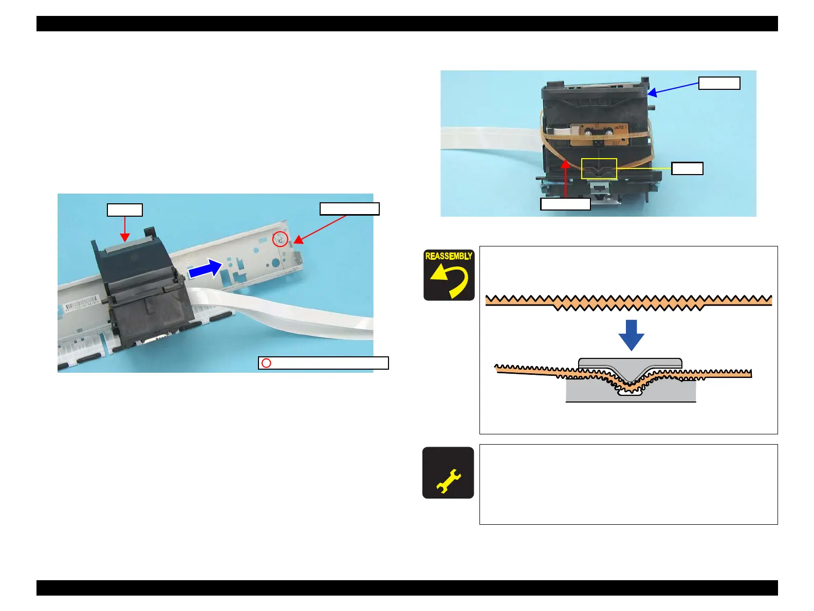
1. Remove the screw (x1) that secures the CR Scale Holder, and remove the CR
Scale Holder.
2. Move the CR Unit in the direction of the arrow to remove the CR Unit.
Figure 4-82. Removing the CR Unit (1)
3. Release the Timing Belt from the groove of the CR Unit.
Figure 4-83. Removing the CR Unit (2)
CR Scale Holder
CR Unit
C.B.S. 3x6, F/Zn-3C (8±1kgfcm)
Put the part of the Timing Belt toothed on its both sides into
the groove of the CR Unit.
Figure 4-84. Installing the Timing Belt
A D J U S T M E N T
R E Q U I R E D
Whenever the CR Unit is removed/replaced, the required
adjustments must be carried out.
• Chapter 5 “ ADJUSTMENT” (p.161)
After replacing the CR Unit, be sure to perform the required
lubrication.
• Chapter 6 “ MAINTENANCE” (p.175)
Timing Belt
Groove
CR Unit
 Loading...