Epson Stylus NX510/515/SX510W/515W/TX550W/NX415/SX410/415/TX410/419/NX215/SX210/215/TX210/213/219/ME OFFICE 510 Revision A
DISASSEMBLY/ASSEMBLY Disassembling the Printer Mechanism 125
Confidential
4.5.11 PF Motor
Parts/Components need to be removed in advance
Document Cover/ASF Cover/Scanner Unit/Panel Unit/Upper Housing/Card Slot
Cover/
Lower Housing
/Main Board Unit/Left Frame/PF Encoder Sensor/PF Scale
Removal procedure
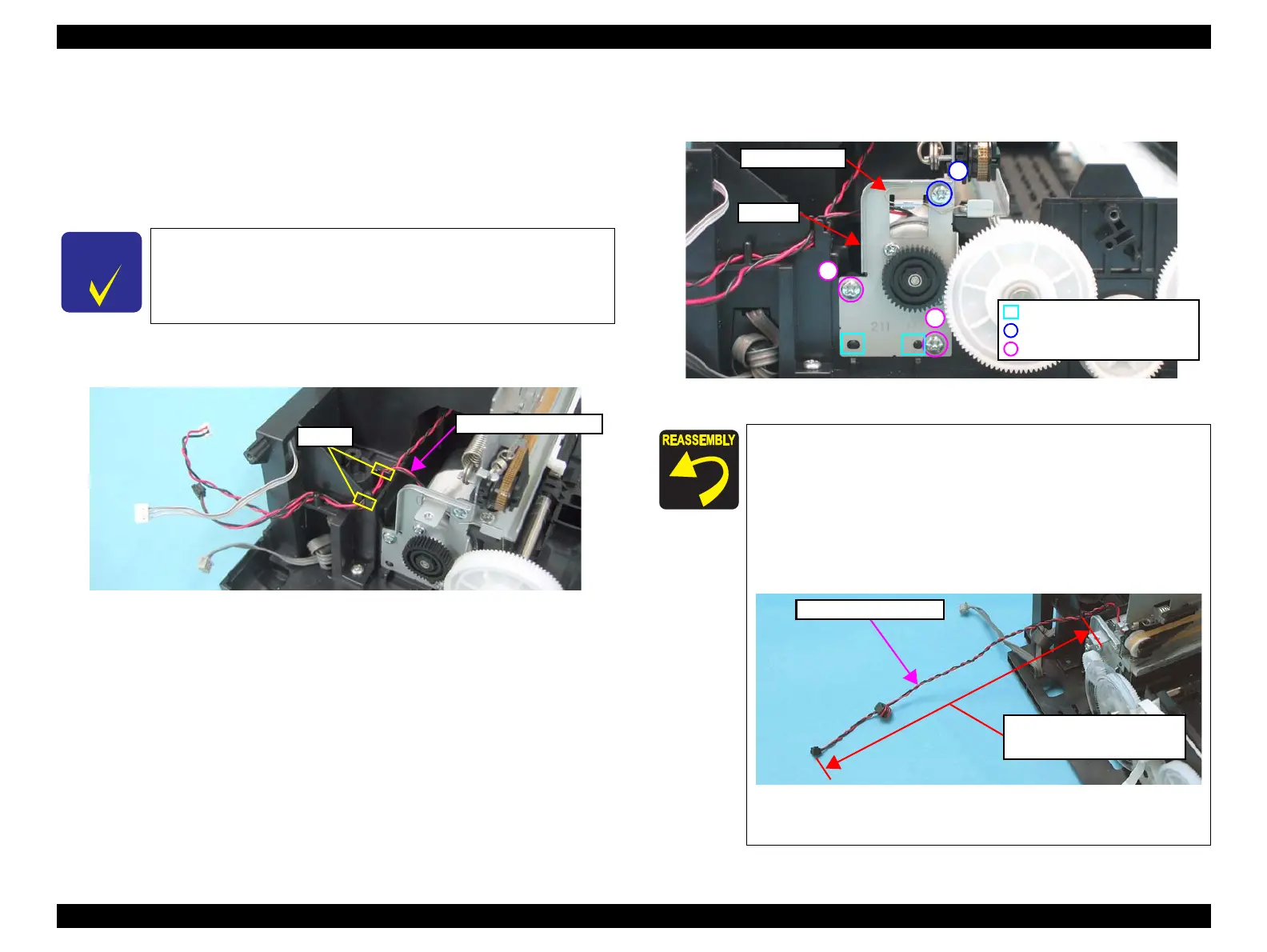
1. Release the PF Motor connector cable from the notches (x2) of the Base
Frame.
Figure 4-67. Removing the PF Motor (1)
2. For SX410/SX210 series : Remove the Grounding Spring from the PF Motor.
3. Remove the screws (x3) that secure the PF Motor, and remove it.
Figure 4-68. Removing the PF Motor (2)
In this section, some disassembling procedures differ between
models. Skip the model-specified steps if not applied to your
model.
Notches
PF Motor Connector Cable
When installing the PF Motor, pay attention to the following
instructions.
• Do not damage the PF Scale.
• Insert the guide pins (x2) on the Base Frame into the
positioning holes (x2) of the PF Motor as shown in
Figure
4-68.
• Route the PF Motor Connector Cable as shown in the figure
below.
Figure 4-69. Routing the PF Motor Connector Cable
Tighten the screws in the order given in Figure 4-68.
C.B.P. 3x8, F/Zn-3C (6±1kgfcm)
Grounding Spring
PF Motor
Guide Pin and Positioning Hole
1
2
C.B.S. 3x6, F/Zn-3C (8±1kgfcm)
3
PF Motor connector cable
N
X
5
1
0
s
e
r
i
e
s
:
1
8
.
5
m
m
o
r
m
o
r
e
S
X
4
1
0
s
e
r
i
e
s
:
1
1
.
5
m
m
o
r
m
o
r
e
S
X
2
1
0
s
e
r
i
e
s
:
1
4
.
5
m
m
o
r
m
o
r
e
 Loading...