Epson Stylus NX510/515/SX510W/515W/TX550W/NX415/SX410/415/TX410/419/NX215/SX210/215/TX210/213/219/ME OFFICE 510 Revision A
DISASSEMBLY/ASSEMBLY Disassembling the Printer Mechanism 128
Confidential
4.5.13 Main Frame Assy
Parts/Components need to be removed in advance
Document Cover/ASF Cover/Scanner Unit/Panel Unit/Upper Housing/Card Slot
Cover/Lower Housing/Main Board Unit/Left Frame/Front Frame/Right Frame/CR
Motor/CR Scale/Hopper
Removal procedure
1. For SX410/SX210 series: Remove the Grounding Spring from the PF Motor.
(Refer to 4.5.11 PF Motor Step2 (p125))
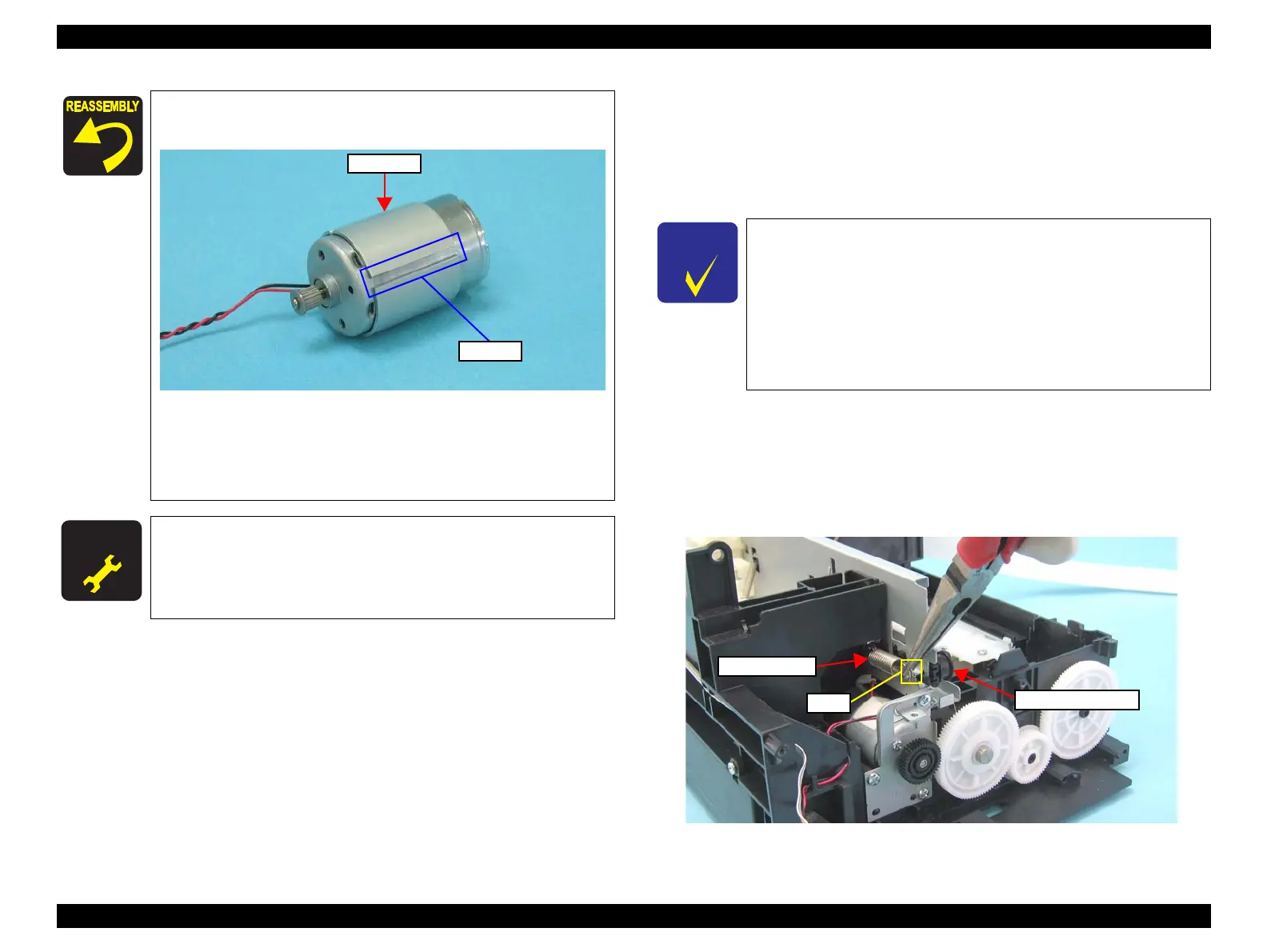
2. Release one end of the Extension Spring from the hook of the Main Frame
with longnose pliers, and then remove the spring together with the Driven
Pulley Holder.
Figure 4-75. Removing the Extension Spring and Driven Pulley Holder
Be sure to install the CR Motor so that the groove on it faces
downward.
Figure 4-74. CR Motor
Tighten the screws in the order given in Figure 4-73.
Make sure that there is no gap between the CR Motor and the
Main Frame.
A D J U S T M E N T
R E Q U I R E D
Whenever the CR Motor is removed/replaced, the required
adjustments must be carried out.
• Chapter 5 “ ADJUSTMENT” (p.161)
In this section, some disassembling procedures differ between
models. Skip the model-specified steps if not applied to your
model.
Main Frame Assy consists of the following parts.
• Main Frame
• CR Unit
• Printhead
• Upper Paper Guide
Extension Spring
Driven Pulley Holder
Hook
 Loading...