Epson Stylus NX510/515/SX510W/515W/TX550W/NX415/SX410/415/TX410/419/NX215/SX210/215/TX210/213/219/ME OFFICE 510 Revision A
DISASSEMBLY/ASSEMBLY Disassembling the Printer Mechanism 127
Confidential
4.5.12 CR Motor
Parts/Components need to be removed in advance
Document Cover/ASF Cover/Scanner Unit/Panel Unit/Upper Housing/Card Slot
Cover/Lower Housing/Main Board Unit/Left Frame/Front Frame/Right Frame
Removal procedure
1. Turn the Spur Gear 51.5 to release the Carriage Lock, and move the CR Unit
to the center.
(Refer to 4.5.1 Printhead Step1 (p113))
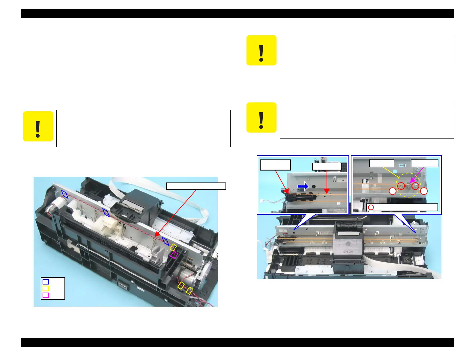
2. Release the CR Motor cable from the notches (x3) of the Base Frame and the
hooks (x3) of the Main Frame, and then pull out the cable through the hole of
the Base Frame.
Figure 4-72. Removing the CR Motor (1)
3. Loosen the tension of the Timing Belt by pressing the Driven Pulley Holder in
the direction of the arrow as shown in the figure, and release the Timing Belt
from the pinion gear of the CR Motor.
4. Remove the screws (x2) that secure the CR Motor, and remove the CR Motor.
Figure 4-73. Removing the CR Motor (2)
Be careful not to damage the CR Motor cable when releasing the
cable from the hooks of the Main Frame.
CR Motor Connector Cable
Notch
Hook
Hole
After releasing the Timing Belt, temporarily secure the belt to the
Cartridge Cover with a tape or the like so as not to allow the grease
to come in contact with the Timing Belt. Contaminating the belt
with grease can result in malfunction of the printer.
Do not damage the pinion gear of the CR Motor.
Timing Belt
Driven Pulley
Holder
Pinion GearCR Motor
C.P. 3x4, F/Zn-3C (4±1kgfcm)
12
 Loading...