Epson Stylus NX510/515/SX510W/515W/TX550W/NX415/SX410/415/TX410/419/NX215/SX210/215/TX210/213/219/ME OFFICE 510 Revision A
DISASSEMBLY/ASSEMBLY Disassembling the Scanner Unit 144
Confidential
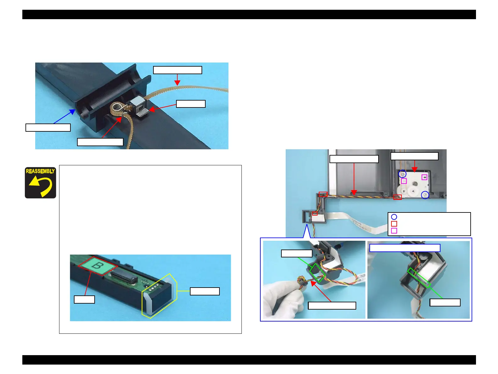
6. Remove the Belt Clamp that secures the Timing Belt.
7. Remove the Scanner Timing Belt together with the Torsion Spring from the
Scanner CR Holder.
Figure 4-123. Removing the Scanner Timing Belt and Torsion Spring
4.6.3 Scanner Motor Unit
Parts/Components need to be removed in advance
Document Cover/ASF Cover/Scanner Unit/Upper Scanner Housing
Removal procedure
1. Move the Scanner Carriage Unit to the center.
(Refer to 4.6.2 Scanner Carriage Unit Step1 (p142))
2. Release the Driven Pulley from the Lower Scanner Housing, and release the
Scanner Timing Belt from the Combination Gear 25.2, 9.0553 and the Driven
Pulley.
(Refer to 4.6.2 Scanner Carriage Unit Step2 (p143))
3. Pull out the ferrite core through the opening (1), and release the Scanner
Motor cable from the hooks of the Lower Scanner Housing.
4. Remove the screws (x2) that secure the Scanner Motor Unit and remove the
Scanner Motor Unit.
Figure 4-125. Removing the Scanner Motor Unit
When installing the Scanner Timing Belt, attach the Torsion
Spring as shown in
Figure 4-123.
When installing the CIS Springs (x2), attach each end to their
positioning tabs (x1 each) of the Scanner CR Holder as shown
in
Figure 4-122.
When replacing the CIS Unit, be sure to replace the spacers
on both ends. Check the label on the CIS Unit and select the
corresponding Spacers as shown below.
• Label A: cis, A17 Spacer
• Label B: cis, B19 Spacer
• Label C: cis, C21 Spacer
Figure 4-124. Replacing the Spacers
Scanner Timing Belt
Torsion Spring
Scanner CR Holder
Belt Clamp
Scanner Motor Unit
Scanner Motor cable
C.B.P. 3x10, F/Zn-3C (5±1kgfcm)
Hook
Scanner Motor cable
Opening (1)
Opening (2)
Installing Scanner Motor Unit
 Loading...