Epson Stylus NX510/515/SX510W/515W/TX550W/NX415/SX410/415/TX410/419/NX215/SX210/215/TX210/213/219/ME OFFICE 510 Revision A
DISASSEMBLY/ASSEMBLY Disassembling the Printer Mechanism 130
Confidential
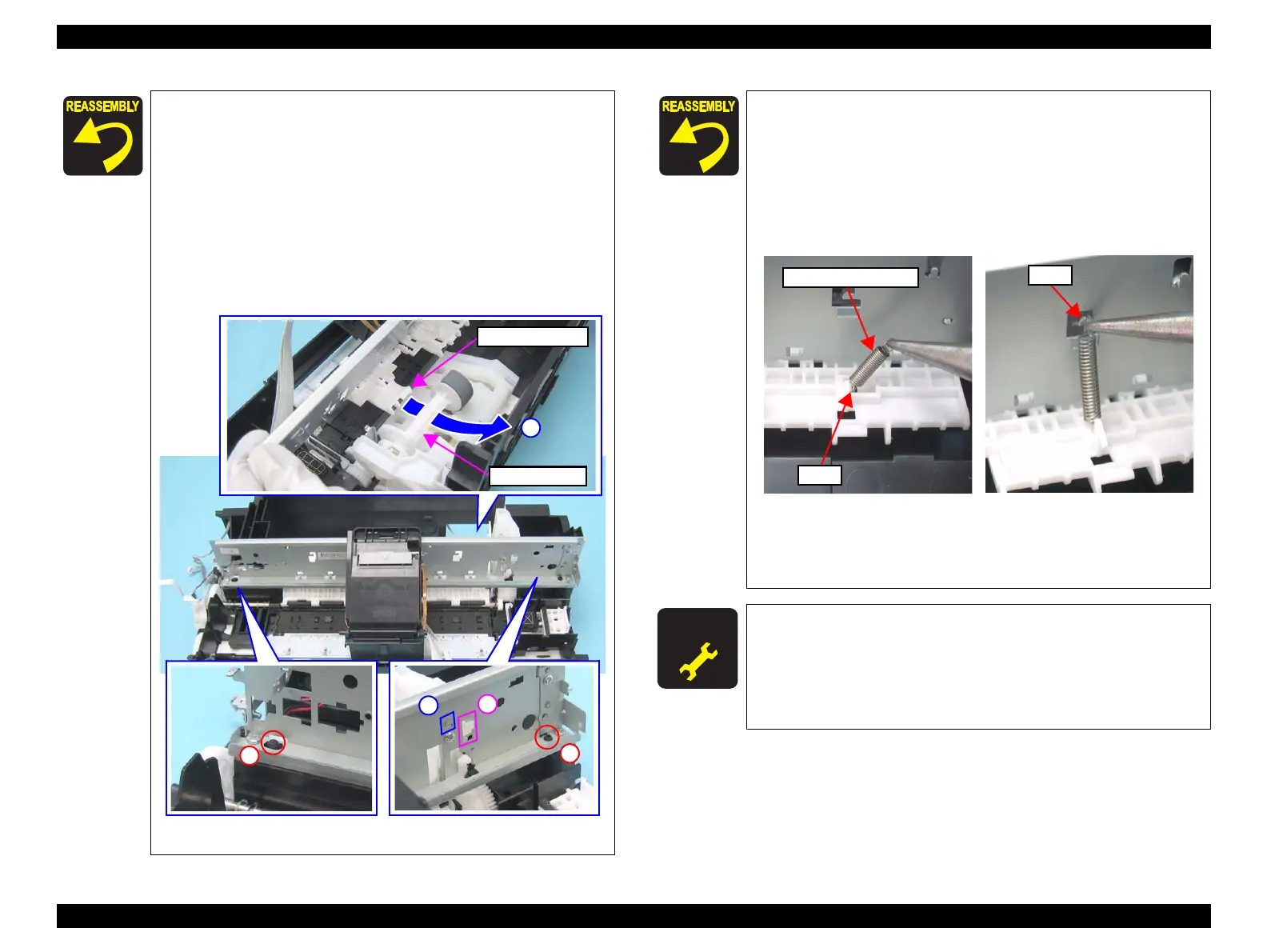
When installing the Main Frame Assy, pay attention to the
following instructions.
1. Put the right part of the Upper Paper Guide under the
LD Roller Shaft as shown in the figure below.
2. Align the hook (x1) of the Frame Support with the
positioning hole (x1) of the Main Frame.
3. Align the hook (x1) of the ASF Unit with the positioning
hole (x1) of the Main Frame.
4. Align the guide pins (x2) of the Base Frame with the
positioning holes (x2) of the Main Frame.
Figure 4-80. Main Frame Assy
LD Roller Shaft
Upper Paper Guide
1
Tighten the screws in the order given in Figure 4-79.
Follow the steps below to install the Extension Spring 10.99 to
the Upper Paper Guide.
1. Attach the one end of the Extension Spring 10.99 to the
hook of the Upper Paper Guide.
2. Attach the other end of the Extension Spring 10.99 to the
hook of the Main Frame with longnose pliers.
Figure 4-81. Installing the Extension Spring 10.99
Be sure to install the Grounding Spring referring to Figure
4-70 and Figure 4-71.
A D J U S T M E N T
R E Q U I R E D
Whenever the Main Frame is removed/replaced, the required
adjustments must be carried out.
• Chapter 5 “ ADJUSTMENT” (p.161)
After replacing the Main Frame, be sure to perform the
specified lubrication.
• Chapter 6 “ MAINTENANCE” (p.175)
Extension Spring 10.99
Hook
 Loading...