EPSON Stylus Photo R1900/R2880/R2000/R2000s/SC-P400 Series Revision I
Disassembly And Assembly Disassembling the Printer Mechanism 103
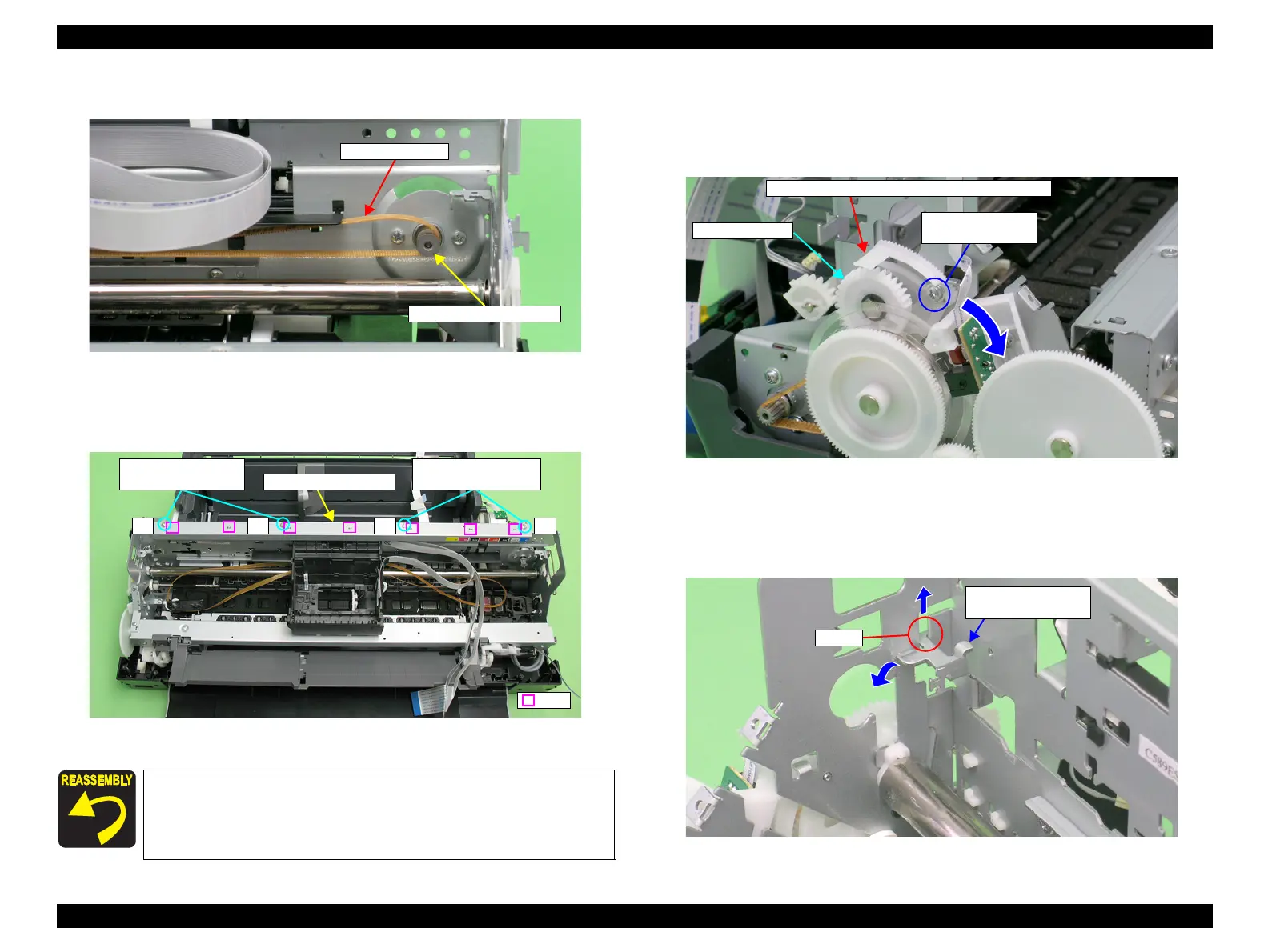
12. Remove the CR Drive Belt from the CR Motor Pinion Gear.
Figure 4-75. Removing the CR Drive Belt
13. Remove the four C.B.S. (P4) M3 x 6 screws that secure the CR Guide Plate, and
remove it from the Main Frame.
Figure 4-76. Removing the CR Guide Plate
14. Loosen the C.B.S. (P4) M3 x 8 screw that secures the Left Parallelism Adjust
Bushing, and rotate the Bushing toward the front of the Printer Mechanism to
prevent interference between the Flag of the Parallelism Adjust Bushing and the
Left PG Cam.
Figure 4-77. Rotating the Left Parallelism Adjust Bushing
15. Slide the Left CR Shaft Mounting Plate upwards, and release the tab on the Left
CR Shaft Mounting Plate from the notch on the Main Frame to rotate the
Mounting Plate toward you.
Figure 4-78. Rotating the Left CR Shaft Mounting Plate
Align the positioning holes on the CR Guide Plate with the
seven tabs on the Main Frame. See Figure 4-76.
Tighten the screws in the order shown in Figure 4-76.
CR Drive Belt
CR Motor Pinion Gear
4 3 2 1
8) C.B.S. (P4) M3x6
(8±1 kgf.cm)
8) C.B.S. (P4) M3x6
(8±1 kgf.cm)
CR Guide Plate
Tabs
6) C.B.S. (P4) M3x8
(5±1 kgf.cm)
Left PG Cam
Flag of the Parallelism Adjust Bushing (Left)
Left CR Shaft
Mounting Plate
Tab

 Loading...


