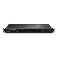
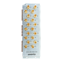
7800 MultiFrame Manual
7812DCDA2Q-HD (-AA, –AES4) Dual Path HDTV Down-converter
Revision 1.0 Page 7
2.1. INPUT/OUTPUT CONNECTIONS
2.1.1. IN A Connector
Description
Program input for processing Path 1. Accepts a 10-bit serial digital video signal
compatible with SMPTE 259M and SMPTE292M standards.
Note: When SD input signals are applied to the card, the input signal is re-clocked
and passed through to both the DA outputs and the program outputs essentially
unmodified (video/audio processing is bypassed with SD inputs)
Connector
Mini DIN 1.0
Impedance
75 ohm nominal
Return Loss
> 15 dB to 1.5 GHz
Cable
Equalization
> 400 m for SMPTE 259M-C input signals (Belden 1694)
> 150 m for SMPTE 292M input signal (Belden 1694A)
2.1.2. DA1A Connector
Description
Re-clocked version of the HD/SD input signal applied to INA.
Output signal is compatible with SMPTE 259M and SMPT292M.
Connector
Mini DIN 1.0
Impedance
75 ohm nominal
Return Loss
> 15 dB to 1.5 GHz
Signal Level
800 mV nominal
DC Offset
0 V ± 0.5 V
Rise/Fall Times
740 ps nominal for SD-SDI outputs
200 ps nominal for HD-SDI outputs
2.1.3. DA2A/6Hz Connector
Description
Dual function and bi-directional. When configured to be an output using VLPRO,
a re-clocked version of the HD/SD input signal applied to INA will be generated
on this output and will be compatible with SMPTE 292M/SMPTE 259M. When
configured to be an input using VLPRO, the module will accept a 6 Hz input that
can be utilized as a 6 Hz reference for both Path A and Path B video
processing.
NOTE: When this input is configured to be a 6 Hz input, the DA4A/GEN BNC
will also be configured as an input.
Connector
Mini DIN 1.0
Impedance
75 ohm nominal
Return Loss
> 15 dB to 1.5 GHz
Output Signal Level
800 mV nominal
Output Signal DC
Offset
0 V ± 0.5 V
Output Signal
Rise/Fall Times
740 ps nominal for SD-SDI outputs
200 ps nominal for HD-SDI outputs
NOTES
SPECIAL NOTES RELATIVE TO TERMINATIONS