DEPOLOX
®
Pool Installation / Commissioning
WT.050.570.000.DE.IM.0714 135
2.7
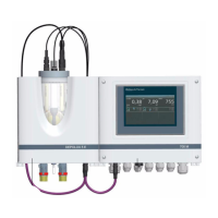
2.7.2 Inserting and Connecting the Sensors
NOTE
On the pressurised version it is not possible to install a sensor for total
chlorine in the cell body.
Fig. 39
1. Remove the protection caps from the sensors.
2. Fit the sensors as shown in Bild 39 into the cover of the cell body.
The sensors are marked as follows:
Cl
2
: Sensor for free chlorine, marked "DES" (2, Bild 39)
pH: Sensor for the pH value, marked "pH" (4)
TC1:
Sensor for total chlorine, marked "Total Chlorine Sensor TC 1" (1)
mV: Sensor for Redox, marked "mV" (3)
µS: Sensor for conductivity, marked "LF325" (5)
When installing the conductivity sensor (5) into a pressurised cell, remo-
ve the plug and the O-ring.
NOTE
Keep the dust protection caps and watering caps of the sensors
for subsequent use.
NOTE
Cable extension:
The sensor cables for Cl2, conductivity and total chlorine may be
extended up to 50 m.
If an extension of the pH or Redox sensor cable is necessary (max.
50 m), an imdedance transformer has to be screwed onto the sensor.
The impedance transformer changes the very high-ohmic sensor signal
into a low-ohmic signal. The impedance transformer has a built-in battery.
The lifetime of the battery is about 5 years, then the impedance trans-
former should be sent to your contractual partner for battery
exchange.