DEPOLOX
®
Pool Description
WT.050.570.000.DE.IM.0714 15
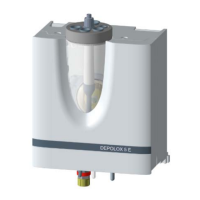
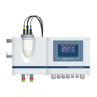
Flow block assembly The flow block assembly (Bild 2) has a plastic housing (2) with a remo-
vable cover.
The housing contains all components of the flow block assembly:
The cell body with cover (1)
The flow control valve (3)
The multi-sensor (8)
The drain (5)
The fine filter (7) (only when membrane sensors are used)
The sample water inlet with check valve and ball valve (6)
The sample water outlet (4) (on pressurised version with ball valve)
The top clips (10) for the sensor and the lower clips (9) for accommo-
dating the buffer or calibration solution can be mounted on the outside
of the housing.
Two mounts are provided for the lower clips.
The cell body can be equipped with up to five sensors (1) on the non-
pressurised version or four sensors on the pressurised version.
Fig. 2 Flow block assembly (cover removed)