154 WT.050.570.000.DE.IM.0714
Installation DEPOLOX
®
5/DEPOLOX
®
4 DEPOLOX
®
Pool
2.10
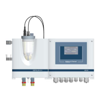
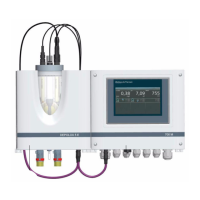
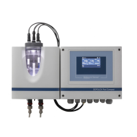
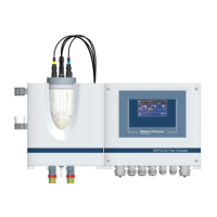
2.10.2 DEPOLOX
®
Pool electronics module with
DEPOLOX
®
4 flow cell module
Connection of a DEPOLOX
®
4 flow cell module is performed in a matter
corresponding to the connection of a DEPOLOX
®
Pool flow cell
module - the same color coding for the wiring is used.
The chlorine measuring cell (red - white - blue - shield+gray) is connec-
ted as indicated in the “Wiring diagrams” on chapter 2.12 on page 164
(module 1 - DES).
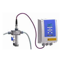
At this configuration, the available flow rate monitor (W3T169826) must
always be replaced with the multi-sensor (W3T166494).
The multi-sensor (white - brown - yellow - green - shield) is connected
as indicated by the “Wiring diagrams” on chapter 2.12 page 163 (gene-
ral inputs).
A Coaxial cable F Drain line (option)
B Impedance converter G Flow rate monitor
C pH and redox electrode H Measuring cell cable (Cl
2
and temperature)
D Housing I Sample tap
E Return J Sample water inlet with check valve
NOTE
During operation with chlorine values of > 1mg/l (e.g. super-chlorinati-
on), it may be necessary to configure a wider µA measuring range on
the DEPOLOX
®
Pool for chlorine measurement (see page page 44).
Please take all further information (technical data, start-up, mainte-
nance,...) referring to the DEPOLOX
®
4 flow cell module from the
"MFA-DEPOLOX
®
4” operating manual.
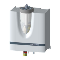
A Drain: G1/2” union nut
B Sample tap
C Inlet: G1/2“ female thread