DEPOLOX
®
Pool Installation DEPOLOX
®
5/DEPOLOX
®
4
WT.050.570.000.DE.IM.0714 153
2.10
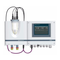
2.10 Installation of DEPOLOX
®
Pool electronics
module with other flow cell modules
The DEPOLOX
®
Pool electronics module can also be operated with
other flow cell modules such as DEPOLOX
®
5 or DEPOLOX
®
4.
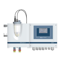
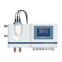
2.10.1 DEPOLOX
®
Pool electronics module with
DEPOLOX
®
5 flow cell module
Connection of a DEPOLOX
®
5 flow cell module is performed in a matter
corresponding to the connection of a DEPOLOX
®
Pool flow cell
module - the same color coding for the wiring is used.
The chlorine measuring cell (red - white - blue - shield) is connected as
indicated in the “Wiring diagrams” on chapter 2.12 page 164 (module
1 - DES). Temperature measurement and the sample water monitoring
systems (white - brown - yellow - green - shield) are connected as indi-
cated in the “Wiring diagrams” on chapter 2.12 page 163 (general in-
puts).
NOTE
During operation with chlorine values of > 1mg/l (e.g. super-chlorinati-
on), it may be necessary to configure a wider µA measuring range on
the DEPOLOX
®
Pool for chlorine measurement (see page 44).
All further information (technical data, start-up, maintenance,...) regar-
ding the DEPOLOX
®
5 flow cell module can be taken from the "MFC”
instruction manual.