Pa.
Sheet
F
E
D
C
B
A
F
E
D
C
B
A
4
3
2
1
4
3
2
1
order number Drawing number
Project
Norm
Checked
Drawn
Date
NameDateRevisionIssue
Date
Urspr. Ers. f. Ers. d.
GER
Prod. / Sales
Design Center
release
Date
Evoqua
Water Technologies GmbH
GER
PB
3
=A1
+S1
Application 1
3
4
5
LAE4703
LAE5573
LAE5900.010
17.06.03
16.01.13
13.05.14
PB
uz
uz
7
8232
WAE
17.06.03
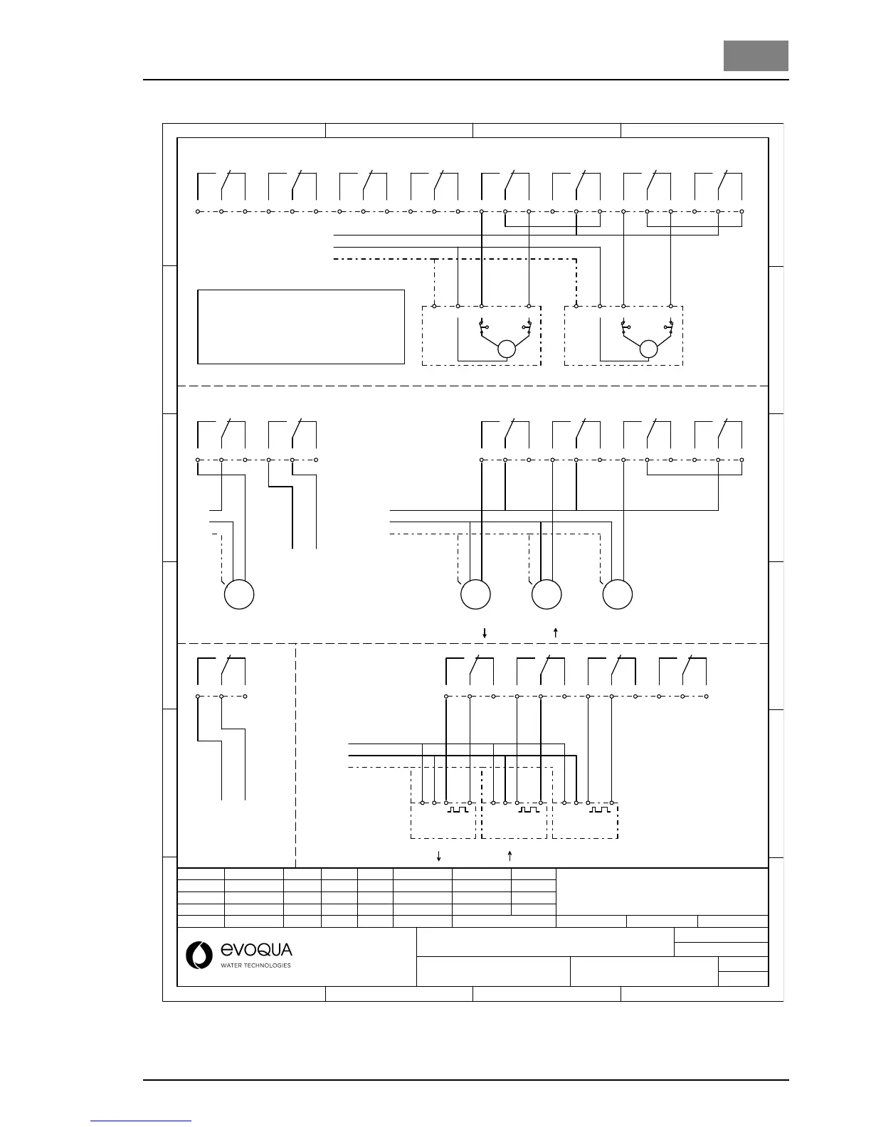
Depolox Pool
PE
L2/N
L1
L1
PE
PE
L2/N
L1
L2/N
PE
L2/N
L1
Relay-Outputs (Application 1)
24 23 22
8
21 20 19
7
18
17
16
6
15 14 13
5
12
11 10
4
98
7
3
3
2
1
1
6
5
4
2
alarm 3 alarm 4alarm 1 alarm 2
open closed
N
M
max
min
PE
Positioner Cl2
open closed
N
M
max
min
PE
Positioner pH
External voltage may
still be connected
even when the main
switch is set to OFF !
DIN-Contact
Flocculation
control
24 23 22
8
21 20 19
7
12
11 10
4
98
7
3
3
2
1
1
6
5
4
2
M
Dosing pump
Cl2
M
Dosing pump
pH
M
Dosing pump
pH
external release
Circulation
reduction
Filter control
M
Flocculent
To prevent starting delay
we recommend to use
pumps with external
enable signal input.
In this case connect
the enable signal input
directly to the
relay contact.
*
L
Pulse triggered
dosing pump
Cl2
pHpH
LN
Pulse triggered
dosing pump
LN
Pulse triggered
dosing pump
12
11 10
4
98
7
3
3
2
1
1
Dosing contact
e. g. for chlorine electrolyser
N
6
5
4
2
4
6
5
2
(Refer to wiring diagram Page 7)
Dosing pump
Connection of inductive
loads (e.g. 1-phase
motor AC) reduces the
contact life of the relay!
Recommendation: Use
metering pumps with
enable input.