DMP 128 Plus • Installation 5
Rear Panel Features and Cabling
100-240V 0.7A MAX
50 - 60 Hz
DMP 128 Plus C V AT
INPUTS
RxTx G
RS-232
+S+V -S G
GIN
1
O1 O2 GIN
2
O1 O2 GIN
3
O1 O2 GIN
4
O1 O2 GIN
5
O1 O2 GIN
6
O1 O2 GIN
7
O1 O2 GIN
8
O1 O2
56
78
11 12
1
2
3
4
9
10
1 2 3
4 5 6 7 8
I/O
OUTPUTS
DMP EXP
ACP
REMOTE
USB AUDIO
RESET
AT
1
(SEC)
2
3
4
(PRI)
LAN/VoIP
1
2
A B C D E F G
H
J K
I
A
Power Inlet
G
RS-232 Port
B
Digital I/O Ports
H
LAN Ports
C
Mic/Line Inputs
I
AT Ports (AT models only)
D
Line Outputs
J
USB Audio Port
E
EXP Port
K
Reset Button and LED
F
ACP Port
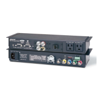
Figure 2. DMP 128 Plus Rear Panel
A
Power Inlet — IEC power connection, 100 to 240 VAC, 50-60 Hz.
B
Digital I/O Ports — Connect up to eight 4-pole 3.5 mm captive screw connectors.
These configurable digital input and output ports are designed to connect to
microphones with logic circuitry for mic mute and tally back functionality. Each port
provides a common ground (see Digital I/O on page72).
In
G
O1
O2
Digital I/O Connector
Figure 3. Digital I/O Connector
C
Mic/Line Inputs — On inputs 1 through 8, use 3-pole 3.5 mm captive screw
connectors to connect eight mono balanced or unbalanced microphone or line level
sources (see figure 4 below for wiring). Inputs 1 through 8 provide AEC (C models only)
and phantom power.
On inputs 9 through 12, use 6-pole 3.5 mm captive screw connectors to connect up
to four mono balanced or unbalanced microphone or line level sources, or two stereo
sources (see figure 5 below for wiring).
(5 mm) MAX. (typ)
16
3-pole Audio INPUT Wiring
Balanced Input
e
Ring
Tip
Tip
Sleeve
Jumper
Unbalanced Input
Figure 4. 3-pole Audio Input Wiring
Tip
ve
Ring
Tip
ve
Ring
Sleeve
Tip
Sleeve
6-pole Audio INPUT Wiring
Balanced Input Unbalanced Input
Jumper
Jumper
Figure 5. 6-pole Audio Input Wiring
figure 2. DMP 128 Plus Rear Panel
figure 3. Digital I/O Connector
figure 4. Audio Input Wiring
figure 5. 6-pole Audio Input Wiring