DMP 128 Plus • Installation 6
ATTENTION:
• Condenser microphones require phantom power.
• Les microphones électrostatiques nécessitent une alimentation fantôme.
• Dynamic microphones do not need power.
• Les microphones dynamiques n’ont pas besoin d’alimentation.
• When a line level source is connected, be certain the +48 V phantom power is
off (cleared).
• Lorsqu’une source de niveau ligne est connectée, soyez certain que
l’alimentation fantôme +48V est débranchée (enlevée).
D
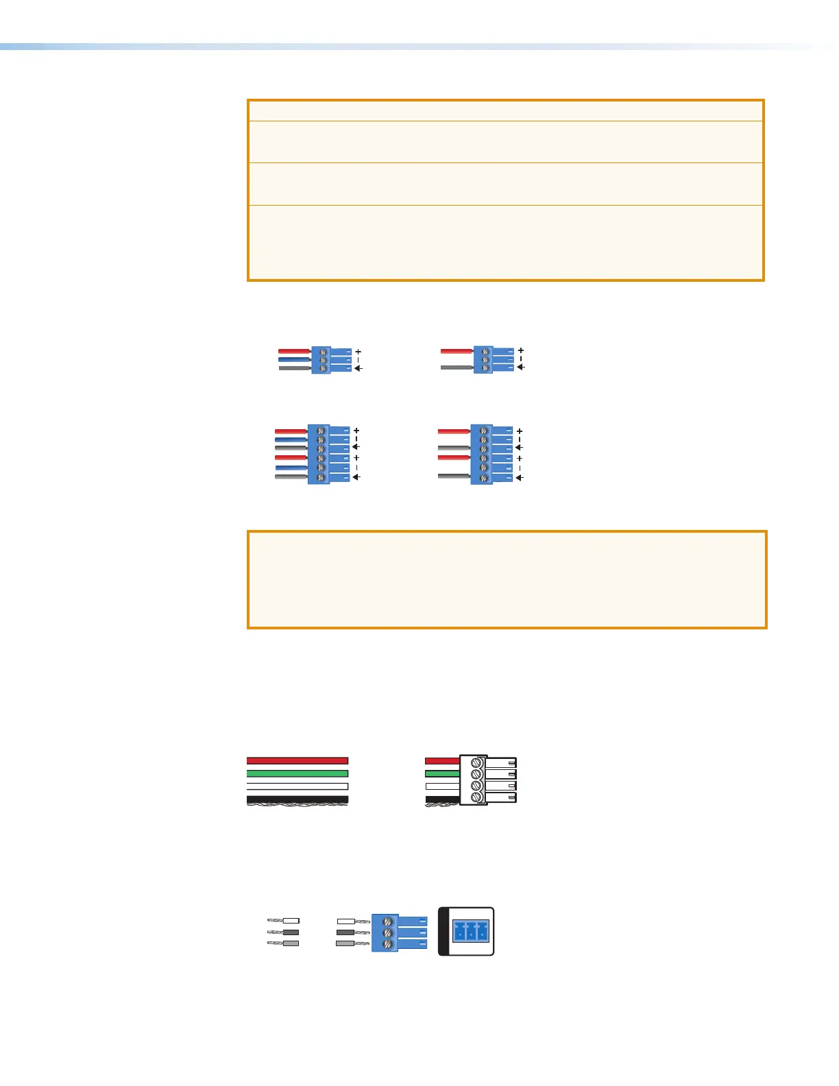
Line Outputs — Use 6-pole 3.5 mm captive screw connectors to connect up to eight
mono balanced or unbalanced line level devices or four stereo devices (see figure 6 and
figure 7 below for wiring).
3-pole Audio OUTPUT Wiring
Unbalanced Output
Sleeve
NO Ground Here
Balanced Output
e
Ring
Figure 6. 3-pole Audio Output Wiring
Tip
Sleeve
Tip
Sleeve
Tip
ve
Ring
Tip
ve
Ring
6-pole Audio OUTPUT Wiring
Balanced Output Unbalanced Output
NO Ground Here
NO Ground Here
Figure 7. 6-pole Audio Output Wiring
ATTENTION:
• For unbalanced audio, connect the sleeves to the ground contact. DO NOT
connect the sleeves to the negative (–) contacts.
• Pour l’audio asymétrique, connectez les manchons au contact au sol. Ne PAS
connecter les manchons aux contacts négatifs (–).
E
EXP Port — One RJ-45 port allows two units to be connected via a shielded CAT 6
cable to form a larger matrix system (1 foot cable included). Any Extron device with EXP
capability can exchange audio with a DMP128Plus via the EXP port.
F
ACP Port — Use a 4-pole 3.5 mm captive screw connector to connect an ACP control
device for configuration via DSP Configurator (see Audio Control Panels (ACP) on
page98).
G
Ground
+ Signal
-
Signal
+12 VDC
+V
-
S
+S
Figure 8. ACP Port Connector Wiring
G
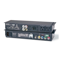
RS-232 Port — Use a 3-pole 3.5 mm captive screw connector to connect the host
RS-232 cable for bidirectional RS-232 (±5V) serial control (see figure 9 below for wiring).
The default baud rate is 38400.
RS-232
Tx Rx G
TE
Transmit
Receive
Ground
Tx
Rx
G
Figure 9. RS-232 Wiring Example
figure 6. Audio Output Wiring
figure 7. 6-pole Audio Output Wiring
figure 8. Control Panel Port Connector
figure 9. RS-232 Wiring Example