DTP CrossPoint 84 Series Matrix Switchers • Installation 20
Analog audio output connectors
Connect audio devices, such as an audio amplifier or powered speakers, to these
3.5 millimeter, 5-pole captive screw connectors. These connectors output the tied
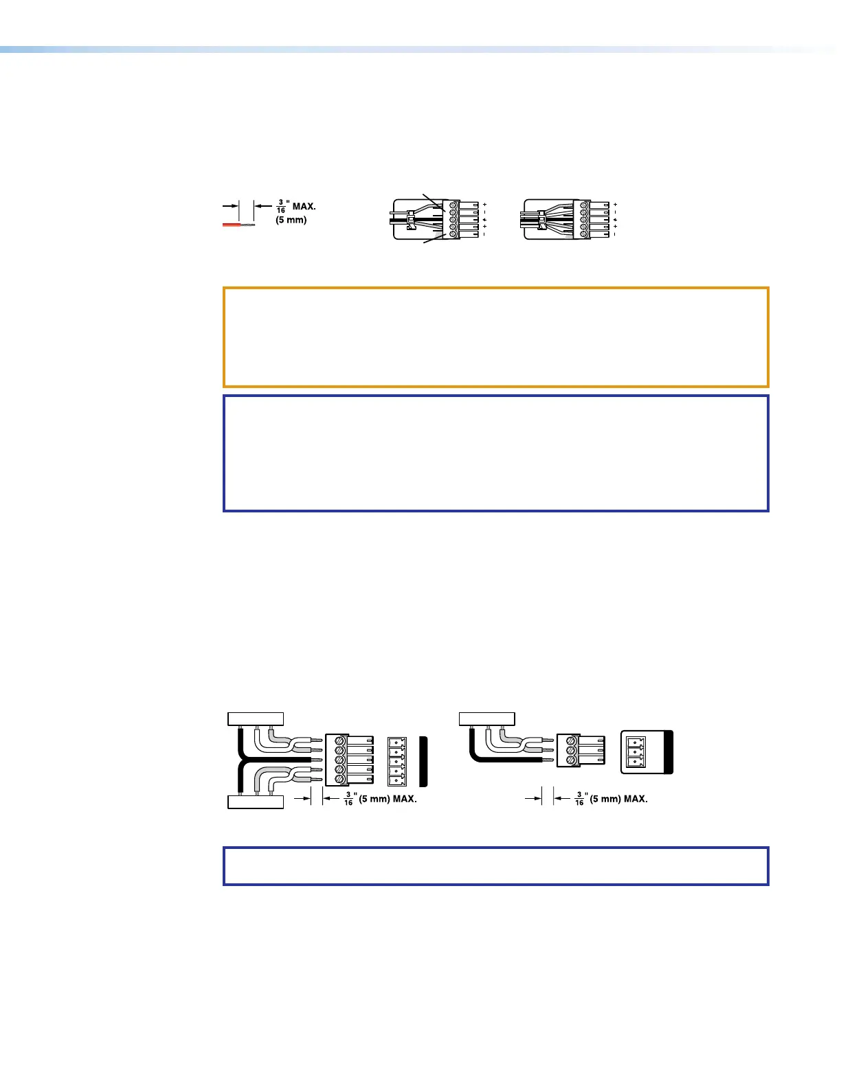
unamplified, line level audio (see figure13 to wire an output connector). Use the supplied
tie-wrap to strap the audio cable to the extended tail of the connector.
Unbalanced Stereo Output Balanced Stereo Output
Do not tin the wires!
Tip
NO GROUND HERE
Tip
LR
Sleeves
Tip
Ring
Tip
Ring
Figure 13. Captive Screw Connector Wiring for Audio Outputs
ATTENTION:
• For unbalanced audio, connect the sleeves to the ground contact. DO NOT
connect the sleeves to the negative (-) contacts.
• Pour l’audio asymétrique, connectez les manchons au contact au sol. Ne PAS
connecter les manchons aux contacts négatifs (-).
NOTES:
• The length of exposed wires is important. The ideal length is 3/16 inch (5 millimeter)
(see the audio input connector NOTES on the previous page for details).
• The audio that is output on these connectors is converted from the tied embedded
input signal or the analog audio input. This feature allows you to duplicate the
outputs while eliminating the need for extra receivers.
By default, the audio ties follow the video ties. Audio breakaway, which can be activated
via the front panel or under remote control if, in the DSP Configurator, the Output Signal
Source is set to From DSP (see Output signal processor chain, Volume controls on
page97), allows you to select from any one of the audio input sources and route it
separately from its corresponding video source (see Example 3: Remove a tie from a set
of ties on page32). You can also use an SIS Command (see page56) or the Product
Configuration Software (see Matrix Software on page70).
Serial and IR port connectors
Figure 14 shows how to wire the Over TP RS-232 and IR and Remote connectors.
Tx/Rx
Pins
Rx Tx
Tx Rx
Gnd
Gnd
RS-232 IR
Tx Rx Tx RxG
OVER TP
TxGnd
Rx
Tx Rx G
REMOTE
Figure 14. RS-232 and IR Connectors Wiring
NOTE: The length of exposed wires is important. The ideal length is 3/16 inch
(5 millimeter) (see the audio input connector NOTES on the previous page for details).
13
14